
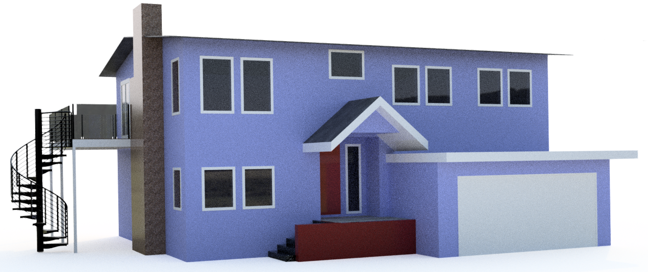
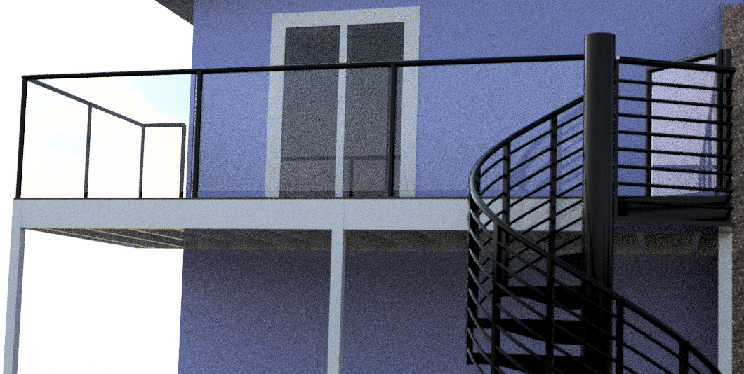
Late last year, I embarked on a process to add a circular staircase to (and rebuild) my exterior deck. While the heavy lifting of pouring new concrete footers and hoisting the steel column into place is outside my realm of expertise or interest, fabricating the uniquely-shaped stair treads definitely is in my wheelhouse.
So I engaged with a general contractor - Mike Miranda, highlighted in this earlier post - who was happy to collaborate with me on some of the work. And during the shelter-in-place we are all struggling thru, I was glad to have a project to keep me occupied for a few days - I figured once I started in earnest, it’d be about three days of work.
In this post, I’ll describe the steps involved to mill and install custom Ipe stair treads, and some of the unexpected problems. For anyone who has done a project like this - which I hadn’t - would know, this is largely a story of jigs.
Jig#1: Full Tread Template
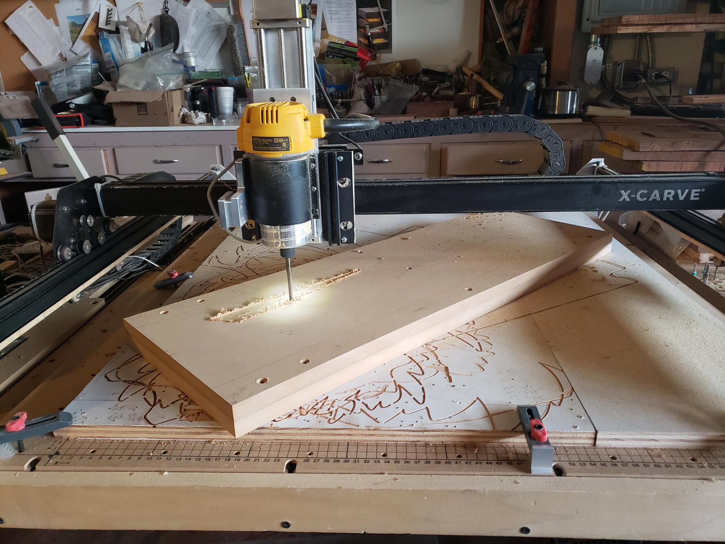
The stair supplier provided a full size paper template, albeit for whatever reason, they elected to leave off a few key dimensions from their drawing. So my first step was to use a ruler and calipers to recreate the drawing in Fusion 360. With this, I could then mill a full size wood template to test if my drawing is correct; this jig will also do double duty as a future hole-drilling template to drill into the aluminum stairs into which the treads will be mounted.
It took three attempts. My first version had a simple measurement error on my part. My second version had a more unique problem: having never CNC’d anything so large - or for which dimensions were so critical - I had never validated the precision of my machine. But over a 30” x 30” square, my CNC had a 0.5% dimension error - or about 1/8”.
So I had to change a few of the parameters on my XCarve that tell it how many millimeters are in each motor “step”. Detailed guidance on how to adjust those can be found in this useful document.


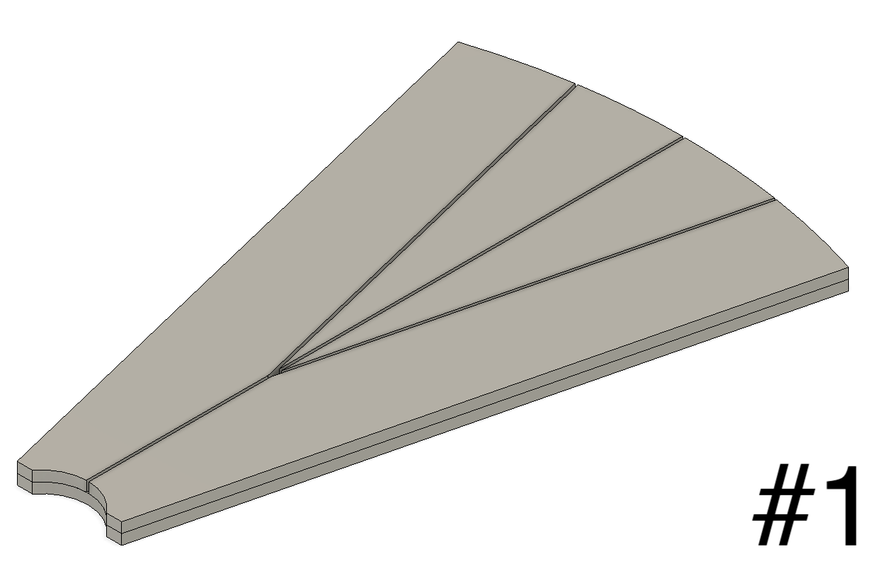
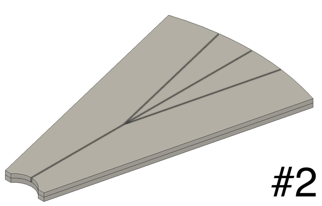
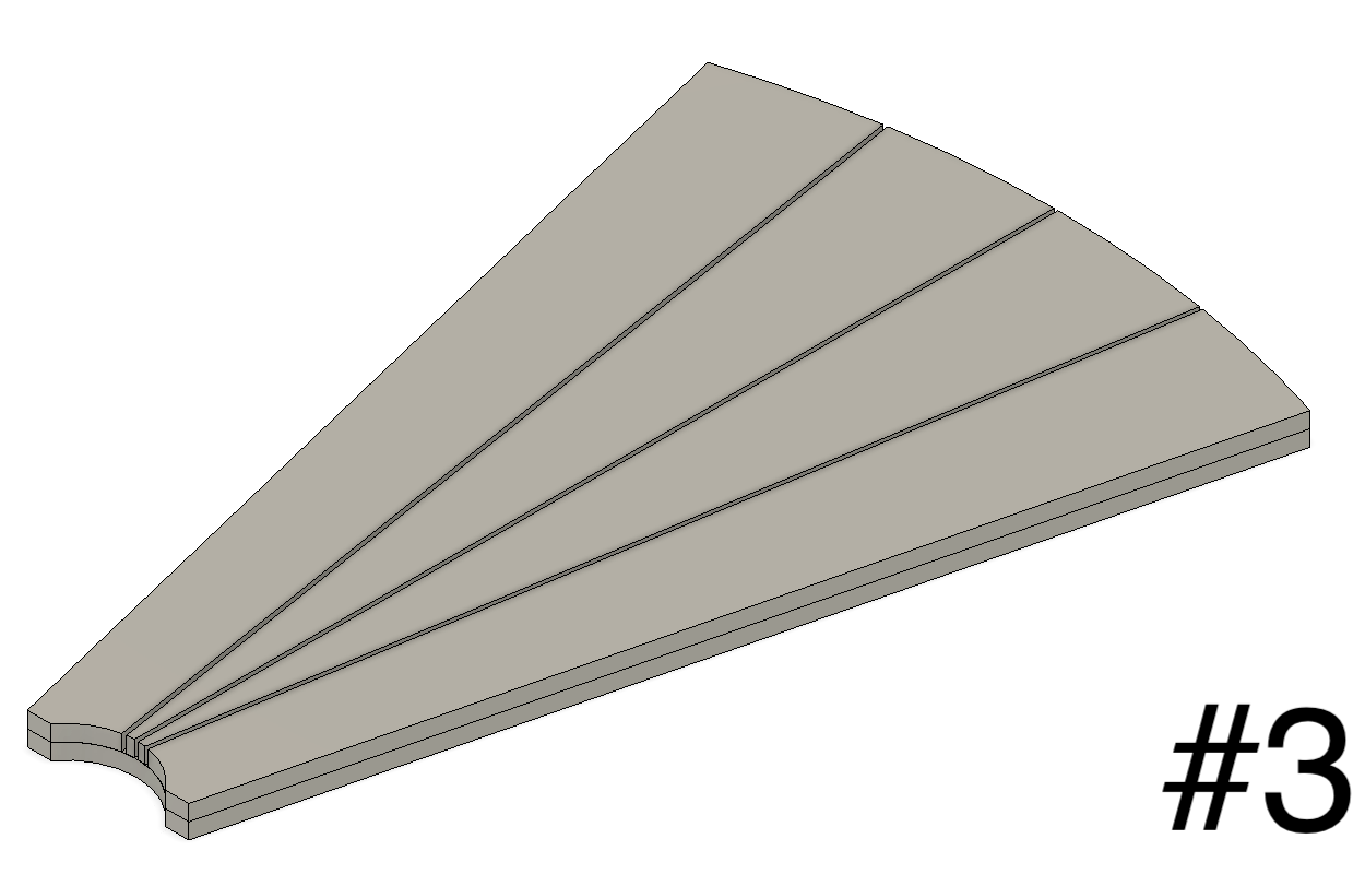
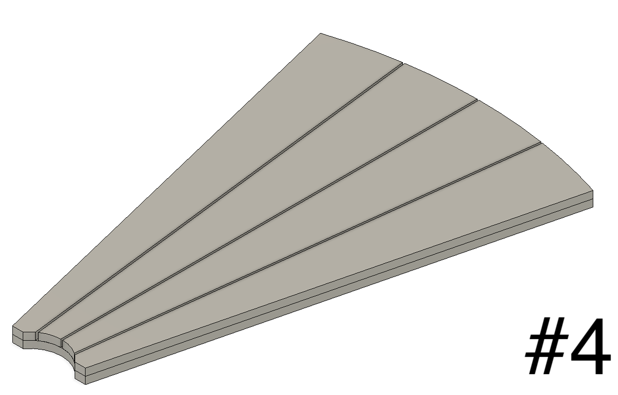
With this overall template figured out, I could now focus in on the tread design. I had earlier drawn up four potential designs, quickly ruling out #2 & #3 based on appearance. Though I really liked the angles in #1, the sharp point of the center pieces provides a more fragile element to the tread that might rot and degrade more quickly - and those middle pieces provide less surface area for attachment to the metal frame. So I zeroed in on #4.
Jig#2: CNC Clamping Jig
Now it’s time to figure out how to cut the four pieces for each tread. While the CNC is obviously the solution for the unique curves and angles at the end of each board, I don’t want to use the CNC to cut out the long straight sides, for multiple reasons:
Clamping: if the cutting head goes around all (or three) sides of the tread, it makes clamping the tread in place much more difficult.
Efficiency: a long straight edge is much faster to cut with a table saw than a CNC, and puts a lot less wear on my equipment.
So I’ll feed pre-cut “pizza slice” wedges to the CNC. That means I need a jig to hold those wedges to serve multiple functions:
Easy to clamp and remove the treads into a precise and repeatable location, since I’ll need to make 52 pieces
Verifies the angle & size of the wedges to minimize wasted effort
Allows the ends to easily fall away as they are cut off
In comes this jig design, made of a 1-1/2” thick MDF block which I created by laminating two pieces of 3/4” MDF.
About ten hours of milling later, I have a jig - and a layer of nasty MDF dust over my entire workshop, which gets me to repairing my CNC dust collection system, a story for the next blog.
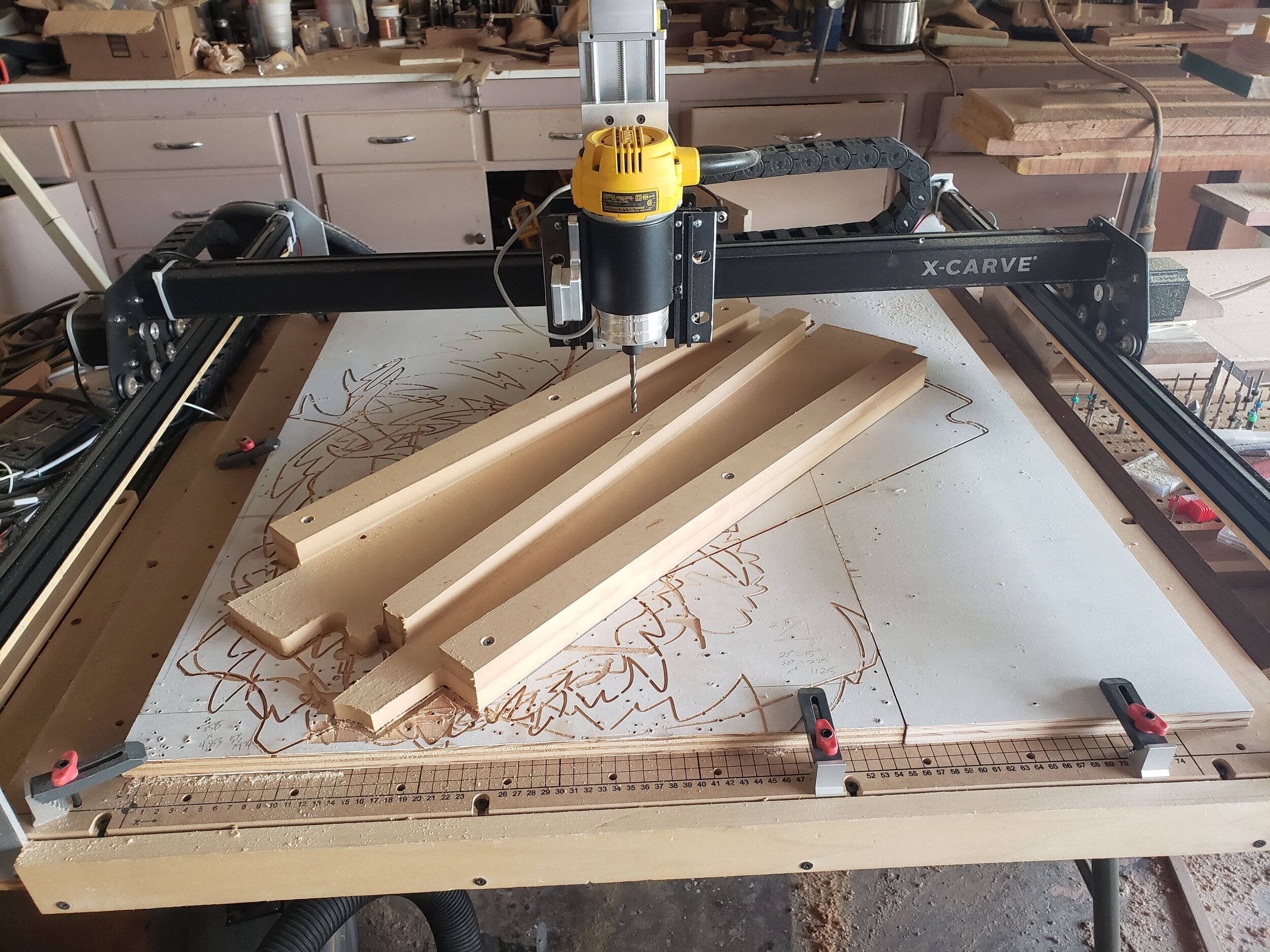
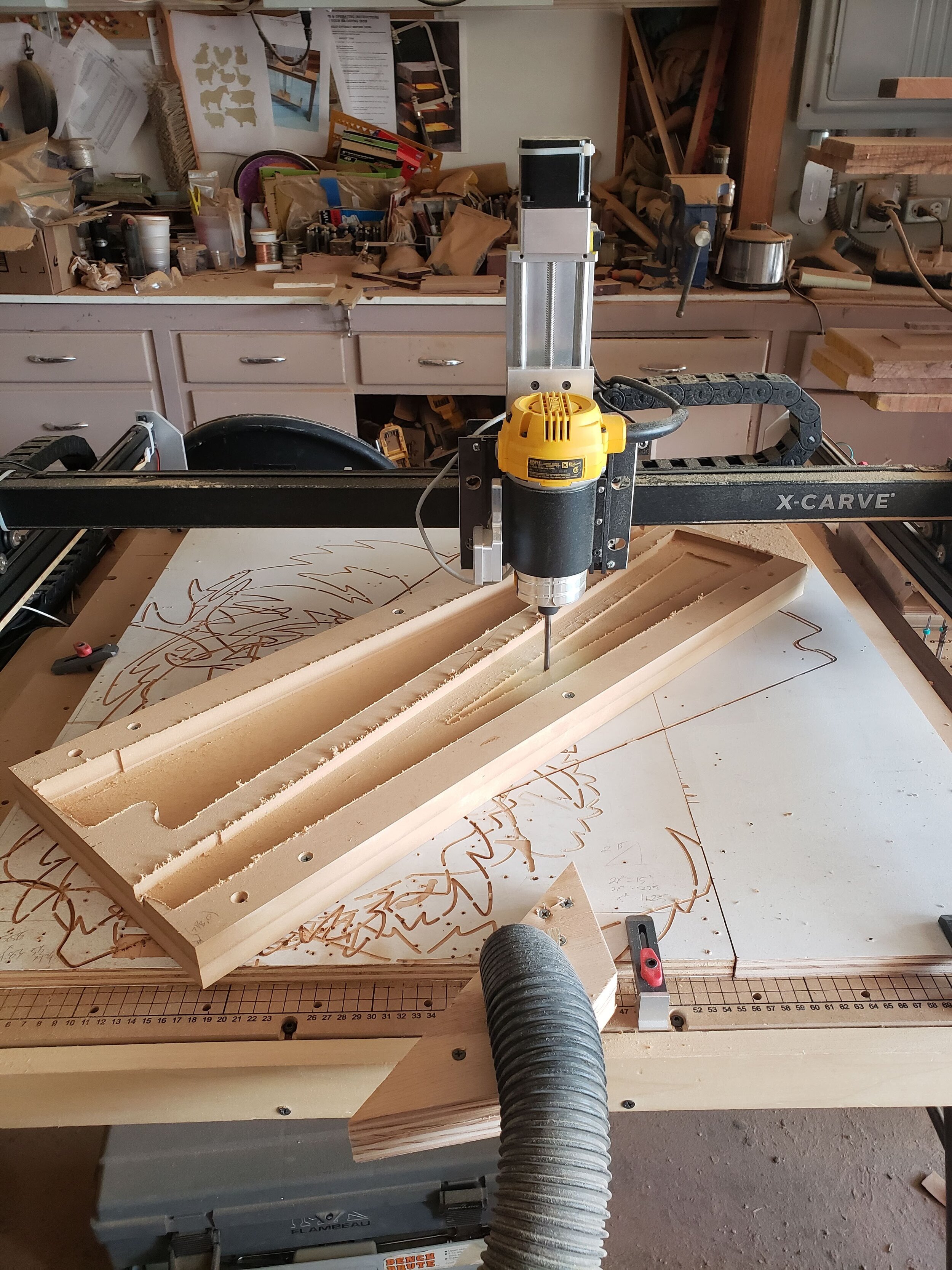
Jig#3: Wedge-Cutting Jig
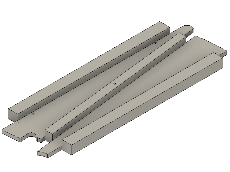
How am I going to create those pizza slices? The basic idea is in this YouTube video. But instead of eyeballing the angle, or a rough measurement, I needed a precise 5.4 degree wedge. A 0.2 degree error in the angle will produce a board that is an 1/8” too wide or too narrow, definitely something that would be noticeable. So I turn again to the CNC to create this jig, positioning the stock diagonally on my CNC bed so that I can get as much of the 48” length in my 30” x 30” CNC work area as possible; the last 10” or so, I cut out with a track saw.

Jig#3; the CNC was able to mill out everything up to the chevron shape in the upper right; the last foot or so I cut with the track saw.

You can see the jig in the middle of this image right next to the table saw blade; the wedges at the bottom of the image are my tests using it with some extra lauan.
Testing All the Pieces
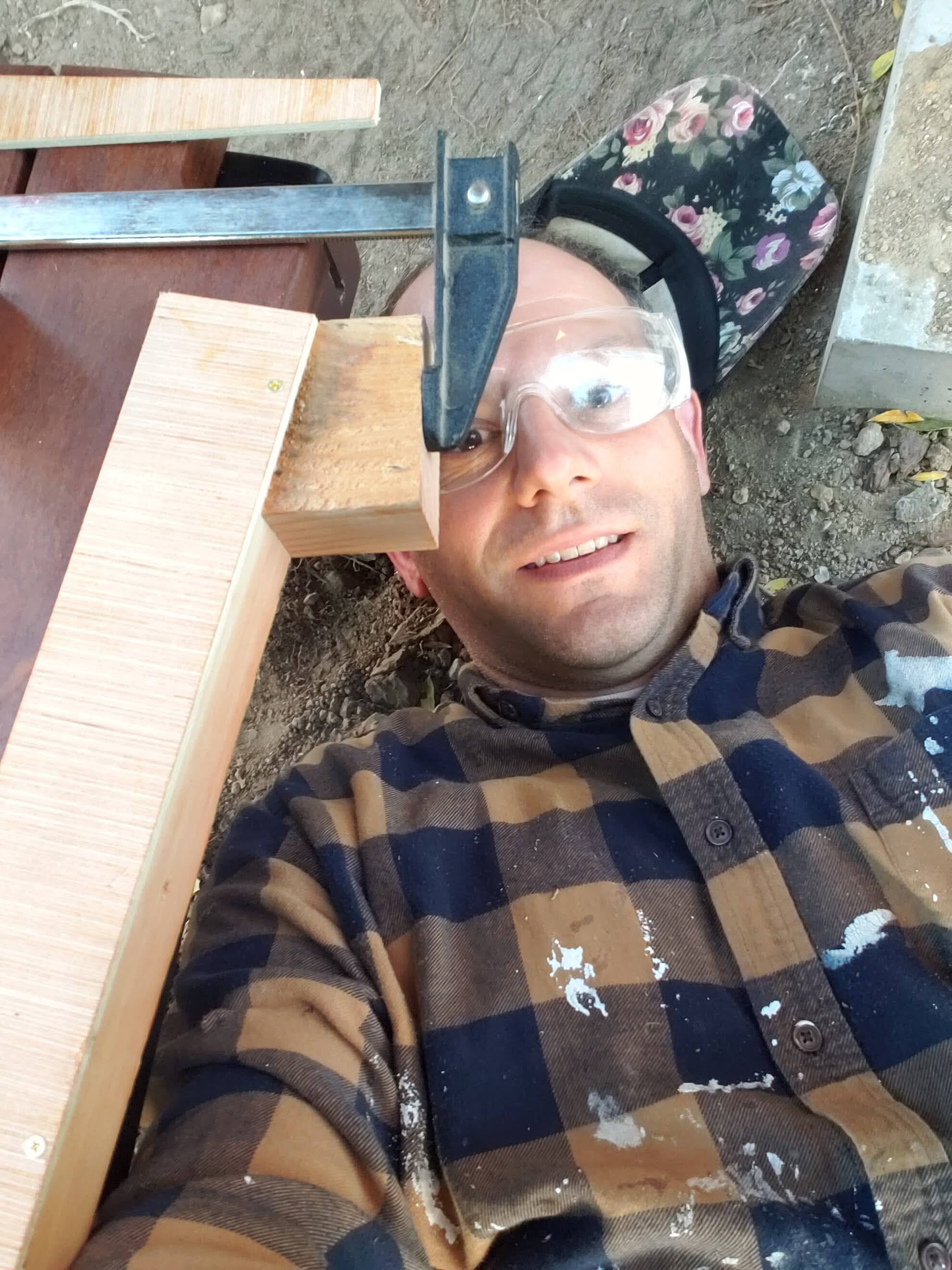
20 hours of design and fabrication time into the process, I’m getting a little nervous about whether all the pieces will come together; it’s time at last for a full test.
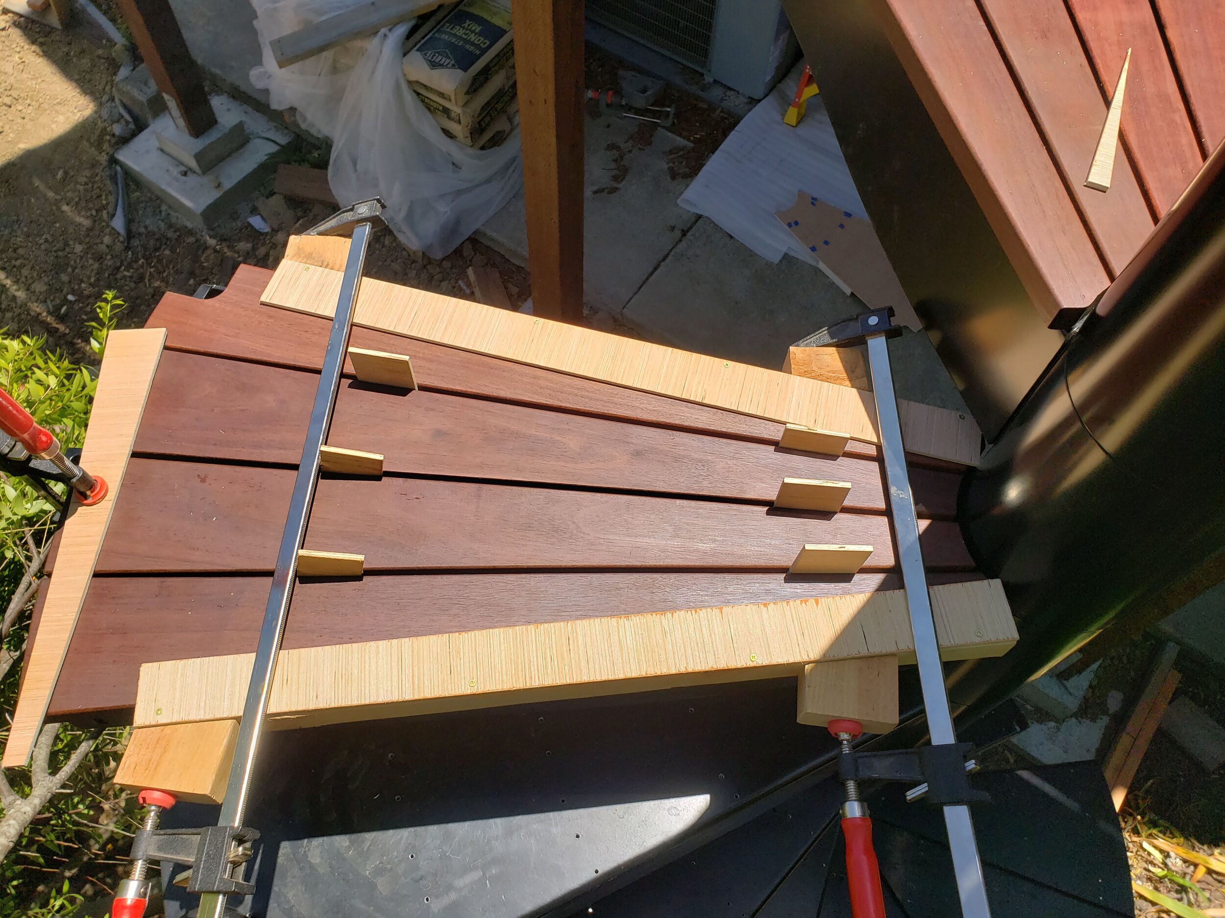
Each pair of the wedges I cut above fits snugly into the clamping jig - the first test works! I clamp the wedges down, and in a few minutes, they’ve been turned into stair treads. All looks good so far, but time for the fit test.


Indeed, they fit perfectly on the original paper template; I’m ready to mill the 52 treads! Doing one last check, I attempt to fit the overall template to the aluminum stairs sitting in my driveway waiting assembly, and there might be a problem!

The stair manufacturer may have sent the wrong paper template?! Because the staircase components were mostly hidden in boxes and bubble wrap, I decided to wait a few weeks until my general contractor has put the center column and steps in place, in case I’m missing something obvious about how the treads rest on the stairs.
Two weeks later, when I’m finally in a position to test, it’s confirmed that I have the wrong paper template: all that work for naught. After a few conversations with the Pennsylvania manufacturer, I have an updated template. I first check it against the stairs to avoid a repeat - this time, it’s correct.
And so, all that work above is repeated one last time. I didn’t take as many pictures the second time around - but if you’re wondering why the treads in the next set of pictures don’t match some of the earlier shapes, that’s why.
Tread Fabrication
After re-fabricating all the jigs, I’m finally ready to start cutting the stair treads. It takes a 44” piece of 5-1/2” wide Ipe to make me two 5.4 degree pizza wedges, so six 20’ pieces give me enough for the treads (and the platform). I start carefully cutting the wedges as I feed the CNC in parallel.


One thing that surprised me in the process was that I didn’t chew up as many bits in the machining of the treads as I expected. Ipe is incredibly dense and hard, and I anticipated using a half dozen end mills in the fabrication. But I only used two end mills - perhaps because it was only about 8” of milling the two ends per tread (1/16th of an inch at a time), or only about 35 linear feet in total.
Jig#4: Clamping Jig
Three weeks ago, I had initially expected the actual installation of the treads to take a couple hours at most. But now with the 52 pieces in front of me, I realized it’d take a bit longer. Each of the 13 steps has 38 screws. For each of those 38 screws, I had to: drill a hole through the 1/4” thick aluminum; drill a pilot hole into the Ipe from underneath while the treads are in place; remove the treads to insert a nylon spacer to allow for under-tread airflow and then re-secure the treads in place; and screw in a galvanized decking screw.
This repetitive work is aided by one more jig (in addition to jig#1 for the drilling positioning) to keep the four treads centered on the step and snugly in place as I drill up from underneath.

Finishing Up
Overall, it took about 60 hours over 7 days to fabricate and install the Ipe treads, including the jig time. This excludes the initial incorrect jigs and the troubleshooting phone calls, but it also excludes about 6 hours of tread / jig design time wrapped up in that.
Day#1 (12hrs): Fabricate jig#1 & test; redesign & fabricate jig#2; redesign jig #3
Day#2 (12hrs): Fabricate jig #3; cut pizza wedges and feed them to CNC to fabricate 52 treads
Day#3 (8hrs): Round over edges of treads, relabel, sand, & oil
Day#4 (2hrs): Fabricate jig #4 & drill 484 holes in aluminum
Day#5 (10hrs): Install stair treads
Day#6 (12hrs): Fabricate platform treads & sand / oil deck
Day#7 (3hrs): Install platform treads
This effort far exceeded the initial “three or so days” I had in mind; this pattern so common in projects that psychologists have given it a formal name: the planning fallacy.
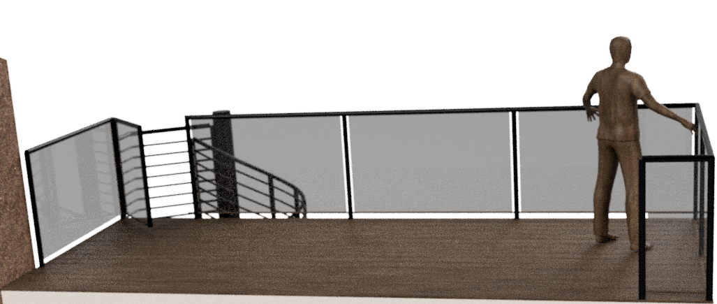
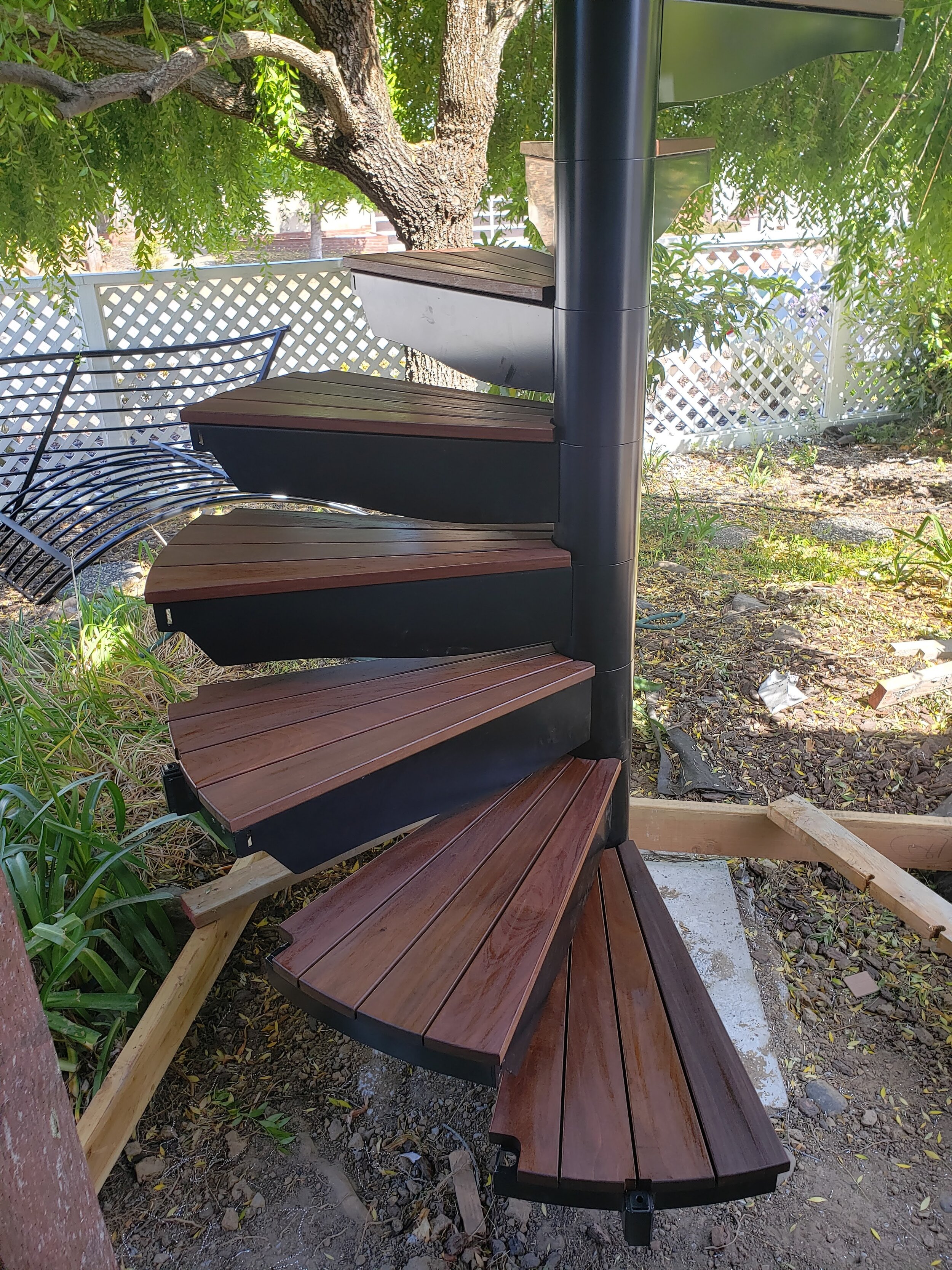
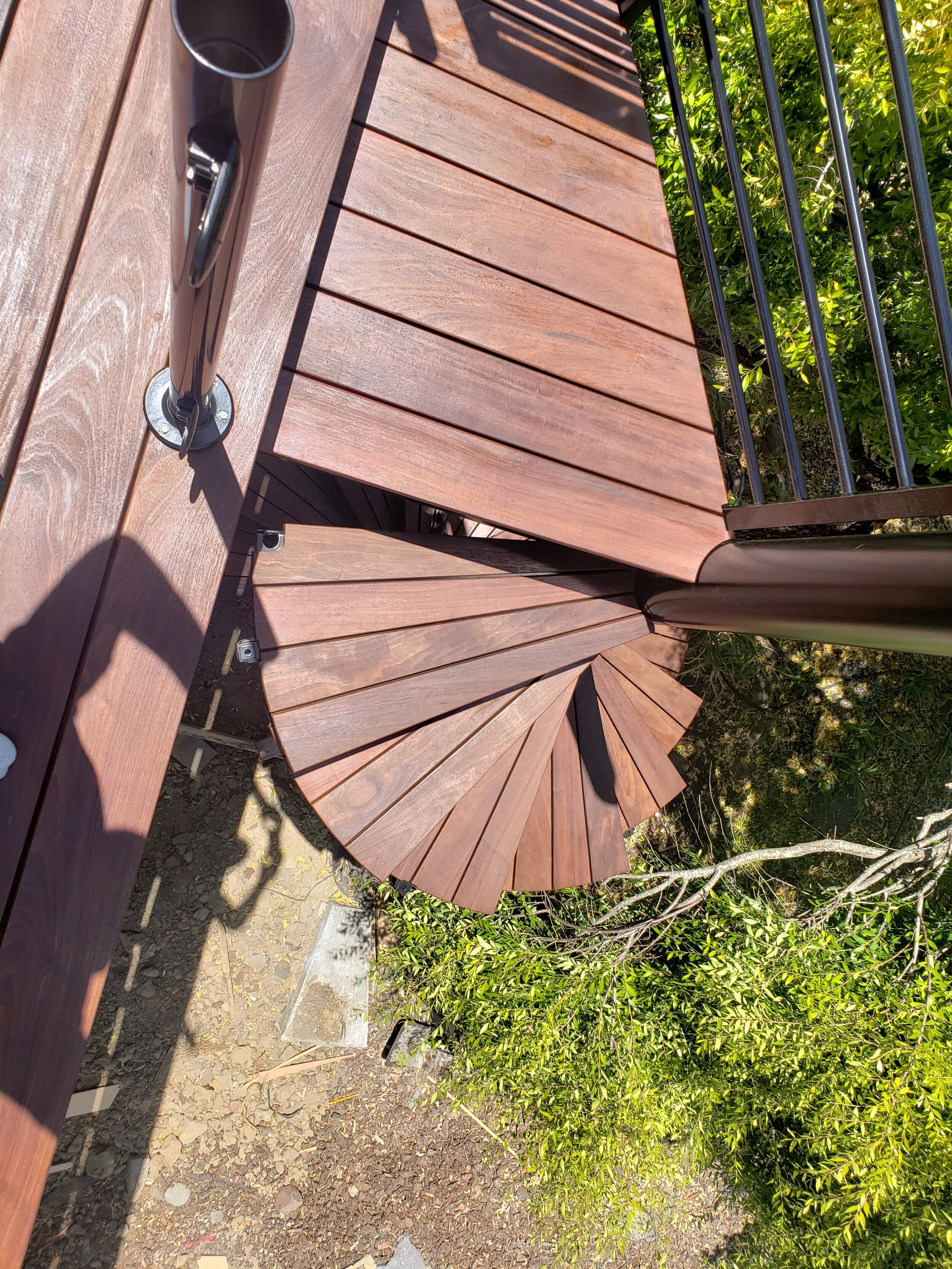
Regardless, I’m very pleased with the results - with the obvious exception of the not-yet-installed railings, it looks pretty darn close to the initial vision.

What big projects have you had opportunity - or need - to tackle given the additional time many of us have had?
I look forward to hearing from you if there’s any projects like this with which I can help!