
Earlier this year, I upgraded my CNC from a X-Carve to a bigger, faster, stronger custom-built machine - you can see loads of details on machine and the process in this three part series covering everything from my thought process in building (vs. buying an off-the-shelf machine), to where I sourced all the components.
Though it has been up and running since early this year, and has completed a few dozen production jobs and countless personal projects, some problems with the stepper motors have continued to plague me. Mostly, this is a missed step here or there that shows up when milling deep pockets in stages, in that the different stages misalign by perhaps 1/100th of an inch. But occasionally a motor just stalls temporarily - even when under no load - so if I’m not babysitting the machine, ready to jump on the emergency stop button, the job will be destroyed.
Most of the time when this has happened, I’ve been able to rescue the job: perhaps its on the interior of an object that will not be seen (such as happened when milling out some plastic for this clock), or it’s early enough in an operation that I’m able to just reposition the home coordinate and mill away the error. But obviously, this does not scale well - and it can be a little nerve-racking when I’m working on an assembly that has had many prior operations that I do not want to muck up.
Surprisingly, the points at which the motors fail are unpredictable and only somewhat related to load and speed - I’ve done a full day of milling deep pockets in hardwood with a 3/8” end mill at 200IPS with no noticeable errors, but a repositioning move (i.e.: no cutting load) at 200IPS further along the gantry’s travel will stall the next day.
Rather than attempting troubleshooting the steppers yet again - see below - it’s time to try a totally different motor technology.
Stepper Challenges
Jogging performance at different voltages.
0:00 - 0:12: Power supply at 48V - see & hear skipped steps
0:12 - 1:17: Adjust power supply to 18V
1:18 - 1:31: No skipped steps for simple back-and-forth
I believe the missed steps are related to the fact that I’m only running the steppers at about 24V instead of their supposed maximum supported voltage of about 50V.
This lower voltage significantly reduces their torque and holding power, but after much trial and error, seemed to be - in combination with some other settings - the sweet spot for the motor while still providing enough power most of the time.
What do I mean by “sweet spot”? For some inexplicable reason, when operating at 50V, the motors gave horrible grinding noises and missed loads of steps. You can see this in the video here.
I spent many many hours trying to troubleshoot this, with multiple phone calls to both the motor supplier (Automation Technology; they confirmed that 48V-54V was the ideal voltage, and in general higher is better up to 54V) and the stepper driver supplier (GeckoDrive; they confirmed their drivers would work between 18V to 80V, and other than the output voltage, there would be no difference in operating characteristics in that range). I made posts to a Facebook Users Group for folks who have the same CNC frame to no avail, and on an electronics forum.
Through these weeks of debugging and dozens of settings, I upgraded the steppers to a higher torque motor; I added chokes to the VFD and stepper power supplies to address potential electrical noise; I added cooling fans to the motor to address a potential heat issue; and I upgraded the power supply to an unregulated overpowered version that should have had zero problem - all to no avail in allowing me to run at a higher voltage.
Ultimately, I found 24V to be the best compromise that mostly worked most of the time; the motors were strong enough to push the gantry against a moderate amount of force I applied manually in testing, and to cut through hardwood at a high speed in practice. But as I never really got to the root cause for why running the motors at the “correct” voltage caused stalling, my fan, cooling, and power supply upgrades, and the settings and setup were just duct tape on some underlying problem.

Stepper with cooling fan mounted and heat sink (on back side) strapped and attached to casing with thermal paste.
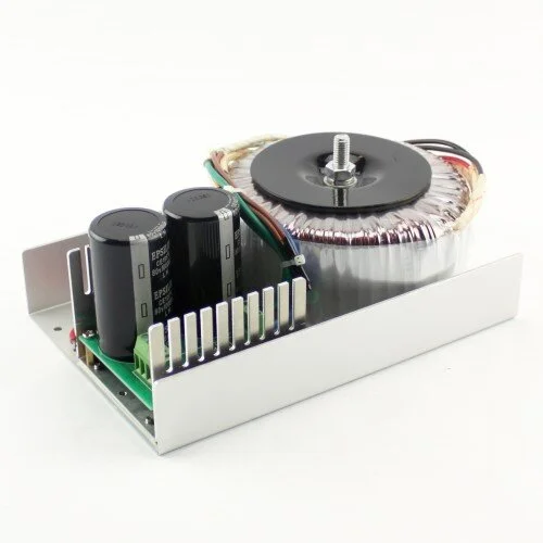
Unregulated power supply I was using after upgrading from a fully variable regulated version; depending on input voltage (120v or 240v) this can supply 24v or 48v DC.
The nitty gritty for those struggling with their own setup: I was using the GeckoDrive 214V driver, initially with the NEMA23 381oz/in 3.5A (KL23H2100-35-4B) and later upgraded to the a 570oz/in 5A model (KL23H2100-50-4BM). Playing with the number of microsteps per revolution, or amperage of the drive, did not materially change the behavior, but i ultimately settled on 5A and 3200 steps per revolution. I initially had a 2000w variable regulated power supply that in theory had more than enough power, but then upgraded to a toroidal unregulated supply that could provide either 24V or 48V, the KL-4820.
Servo Upgrade

The servo installed on left, next to the (removed) stepper with heat sink (and cooling fan partially hidden) on right. The highest power NEMA23 servo was only about a half inch taller than the stepper I removed, even with the integrated controller.
The key functional difference between stepper motors and servo motors is that stepper motors do not give any feedback on their position, whereas a servo motor provides detailed position information to the upstream controller via a built-in encoder. With that information, the servo controller is able to provide additional power, compensating for the load, vibration, or forces acting counter to the desired position. And ultimately, if the servo motor drifts from its expected position for any reason, it can provide an error signal that is recognized upstream by the CNC controller that will halt the job.
Specifically, the motors I purchased (Teknic CPM-SDSK-2341S-ELN) can provide precision to 1/6400th of a revolution; with the screw drive system I have, this translates to a theoretical resolution of 1/13,617th of an inch. However, due to system inertia and natural vibrations that prevent realizing that level of accuracy, I have configured the drivers to send an error signal only if the motors are out of the commanded position by more than 100 steps, or 1/136th of an inch.
And as the servo drivers are monitoring the position continuously during the entire movement, not just at the final position, I now have confidence that the spindle is exactly where the controller thinks it is.

The software oscilloscope on the left - from the Teknic Motor Setup Program - shows the positional error (in red) and velocity error (in blue) for a 300IPS jog that I triggered thru the CNC controller. Over the 2.5 second jog, the position was never off by more than approximately 4 steps or 0.000625 revolutions, or 0.00027”, and the velocity had a maximum error of about 0.2RPM (at a speed of approximately 750RPM). Of course, this is with no load, but it gives a sense of the feedback loop in play that will identify and trigger an exception upon a larger positional error about 25x that, or 0.007”.
The background window in the lower right allows me to view and edit the motor settings, as well as diagnose any potential errors.
But should the servos encounter a positional (or any other) error beyond the user-configured thresholds, the CNC controller (Masso) stops the spindle and requires the machine to be re-home’d before resuming. So now, instead of errors getting carved into the wood, an error will immediately halt the machine until I can diagnose the problem.
A few unexpected bonuses of the servo motors are that they are much quieter, and use much less power (2-10 watts DC, instead of 15-30 watts). And because the servo controller allows for a more dynamic motor acceleration than that built into the Masso controller, jobs with lots of small moves finish much faster as well!
Wiring

I was able to reuse the stepper terminal block and signal cable. At the top of the terminal block are the servo wires:
Servo Black: Step signal, wired to Masso step output of an axis
Servo White: Direction signal, wired to Masso direction output of an axis
Servo Blue & Green: +4-24V (blue to send an enable signal; green for one side of the opto-isolated switch that will close upon an error)
Servo Red: Error signal from motor, wired to a Masso input
Servo Yellow, Brown, & Orange (not seen) wired to a common ground.
The servo motor connectors suggest that 10 conductors are required: 8 for signal, and 2 for power. Even if I were wiring this from scratch, it would be challenging to squeeze all those wires into the drag chain, alongside various other signal, power, and pneumatic feeds. Fortunately, it turns out that 1) the power can be daisy chained, and 2) the 8-conductor signal cable actually carries 4 signals and 4 grounds, which can be collapsed into 4+1 conductors.
So instead of running (8+2) x 2 new wires thru the drag chain, I was able to get by with 2 x 4 + ground + power. The existing 4-conductor stepper cable carried the signal, and so I just needed to run 3 more individual wires for the logic ground and for the motor power, with custom-configured connectors to patch those feeds into the motor connectors.
Tuning
One different element of the Teknic servo motors is that the motors need to be “tuned” to the mechanics of the system to which they are connected. Teknic provides “auto tuning” software that runs while the motor is connected via a USB cable to a Windows computer. The tuning process is a little scary in that it makes all sorts of clicking and grinding noises as it determines the inertial characteristics of the mechanical system - you can see a video of this on a larger system starting at about the 4 minute mark here.
A complication with my CNC is that the Y-axis is controlled by two independent motors that run at the same speed but on drive screws on opposite sides of the machine, so these motors cannot be tuned independently. Teknic provides instructions on how this type of system can be tuned, but ultimately, I found great results by just loading the Z-axis tuning file to both the Y-axis (and also to the single X-axis) motor.
Cost
Of course, this upgrade does not come without a hefty price tag - each of those four motors was about $500; with the matching power supply, taxes, shipping, and new couplers to the drive screws, it came to about $2500 for the changeover.
That’s pricey even when compared to what I spent across all the stepper motor install and upgrades (initial stepper: $40 x4; upgraded stepper: $50 x4; GeckDrive: $151 x4; power supply: $200 x2), albeit if I would have known of all the days pulling out my hair troubleshooting the steppers from the beginning, I would definitely have started with the servo motors.
Of course, not knowing the original root cause of my stepper failures makes it hard to give definitive guidance for where servos are worth the cost; certainly, I did not expect to run into so many problems with the steppers, and further, it seems many others have had success using steppers with a similar machine. I guess this is just one of the many challenges in building and supporting your own custom CNC.
Results
First, on the key problem area with respect to losing position, the servos seem to be much much better. From some initial high-speed jog testing at 350IPS, my machine does not lose any steps. When testing on a 2.5 million line command file, the steppers invariably lost about 1/8” of position in the x- and/or y-axes by the time the CNC got half way thru the file, whereas the servos got to about 75% complete twice before halting due to a detected motor error. Interestingly, the motor software identified the error as an electrical noise issue, rather than a positional error; this may have been the cause of the stepper problems too, albeit now I can detect, halt, and recover from the error rather than having a multi-hour job destroyed.
Relative silence - compared to the noisier steppers here.
Another minor benefit is that the servos are much much quieter than the stepper - compare the sound in the video here to that of the “functioning” steppers in the earlier video. However, the stepper noise is usually drowned out by the sound of the spindle and / or dust collection, so this does not matter a whole lot.
But an unexpected real benefit is that the servo motors can accelerate and decelerate much faster than the steppers. I was able to significantly increase the Masso acceleration limit, instead relying on the Teknic vibration and resonance suppression algorithms (called RAS, or Regressive Auto Spline) to dampen the acceleration. Though I did not increase the maximum linear speed of any of the axes, this higher acceleration means that jobs with a lot of small moves are materially faster. For instance, that 2.5 million line file, which is carving a 10” x 16” surface with a lot of detail using an incredibly fine mill, previously took about 12-14 hours to complete, whereas now it completes in about 7 hours. Once I upgrade my laptop as well - making adjustments to the geometry with my 8-year old laptop takes over an hour per change! - I look forward to finally being able to cut a small version of this chest.

Original medieval-era chest

Rendering of one of the four pieces I hope to finally be able to carve with upgraded motors and to-be-upgraded laptop!
It was expensive. And it took about a day and a half to replace the motors, build the custom connectors, and run new wiring. But - at least for my needs and given my past stepper problems - it was a project well worth the investment.
Have you had similar problems with steppers, or have any insight to provide on my still-not-understood problems? Or have you made a similar upgrade but for other reasons? If so, I’d love to hear your experience!