
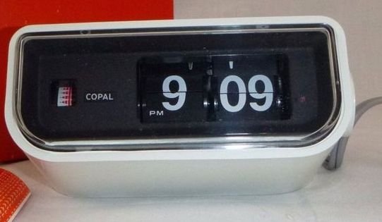
This split flap clock has the simplicity of being driven by a single motor, but is - of course - limited to displaying the sequential numbers of a clock.
Continuing on the theme of kinetic sculptures from last month’s post - and building on the idea of unique display technologies that first piqued my interest when a potential client inquired about Nixie clocks at a local art show back in 2018 - I’ve been exploring the idea of a new kind of mechanical clock. Similar to old-fashioned split-flap clocks of yore, it would be driven by a single motor.
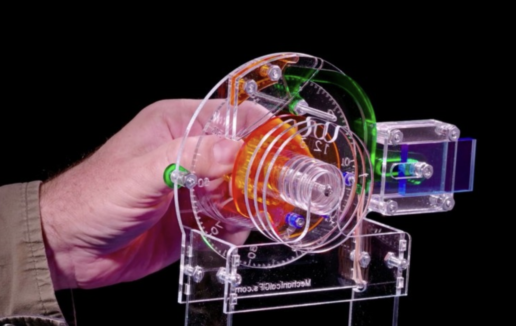
The internal workings of a combination lock reveal how pins protruding between the rings cause one ring to trigger movement on deeper rings.
However, behind that basic outward appearance is a Rube Goldberg-esque level of complexity, because instead of displaying only sequential numbers, the mechanical display is actually a grid of pixels that provides the flexibility to display an arbitrary message. The inspiration for the design came from a German company Rynx, and their approach immediately piqued my interest as a design with both mathematical and fabrication complexity, creating something that looks and like it could have been created in the early 20th century but with digital complexity that really is only possible with modern circuitry.
The idea is based on the concept of an old-fashioned combination lock, but instead of precise spins only lining up the notches in the rings to release the hasp, the rotations line of the patterns printed along the perimeter of the rings in a way that can form a message along an exposed angular slice of those rings. Add more than the three rings of a standard lock, and you can create a message of arbitrary length. And this has a great advantage to the design I was exploring previously, in that it is driven by just one very precise motor, rather than requiring hundreds of motors and sensors!
Foundational Math
If a single ring has n “pixels” visible in displaying a single column of a message, there are 2^n combinations of pixels. That is, if the angular slice that is visible of each ring exposes 5 pixels, there are 32 different combinations of black & white possible. So the first step is to arrange black and white squares around the ring in a way that, stopping a single ring in any of its 32 positions will expose a distinct combination of those squares.

One possible sequence of black (0) and white (1) around a ring that contains all 32 (2^5) combinations when starting in each of the 32 different positions.
For instance, a ring that was half black and half white (i.e.: 0000 0000 0000 0000 1111 1111 1111 1111, where the 0s and 1s represent black and white squares adjacent to each other, and the spaces are just for ease of reading) could not display, say, the semi-colon of a clock (i.e.: 10101, or white-black-white-black-white), no matter how you rotate that ring. So the first step is to figure out a sequence of black and white around a ring that will cover all the possible combinations of pixels. A small bit of code (with a brute-force search) helped me identify that there are 2048 possible ways to arrange black and white around a ring while achieving all 32 bit patterns; one such pattern is 0000 0100 0110 0101 0011 1010 1101 1111.
Display Resolution
Why have I settled on a resolution of five pixels? Afterall, fonts that are only five pixels tall might be somewhat limiting. The samples below show fonts drawn with 3, 4, 5, 6, and 7 pixel heights - 3 and 4 are barely legible; 6 and 7 allow a lot more flexibility and creativity, including bold fonts and lower case letters. 5 pixel-height characters are definitely legible, though - at least initially - not all that attractive.

Size of mechanism (gray) in relation to display resolution (yellow & black) for 5, 6, 7, and 8-pixel displays. Somewhat counterintuitively, the highest resolution display on the right would require the line of text to be tiny in relation to the overall mechanism size.
A 6” diameter tube is about the largest that might be attractive for a tabletop clock (or tabletop message board); a 5” diameter ring can fit comfortably inside a 6” tube with a little extra clearance if needed for some mechanical elements.
A 5 pixel display on a 5” ring that has 32 pixels drawn around its circumference leads to a font that is about 2.5” tall. (Total circumference = 5” * pi = 15.7”; if 5/32 of the ring is visible, so 5/32 of 15.7” = 2.5”.) This also means - to keep the pixels roughly square - that such a ring could be about 1/2” thick, a very reasonable size to work with for 3D printing, press-fit bearings, and general fabrication.
However, at 6 pixels, only 6 of the 2^6 = 64 ring pixels would be visible through a window; the same 5” diameter ring would display a font that is about 1.5” tall (and the rings would have to be about 1/4” thick for a square pixel). And while 8 pixels gives a huge amount of flexibility - most LCD and LED alphanumeric displays are 8 pixels tall for a line of text - would give a line of of 0.5” tall text (and the rings would have to be 1/16” thick).
So 5 pixels seems like it is buildable, legible, and has a large-enough text so that the mechanics of the system do not dwarf the visual output! Additionally, if we are creative in how we define the fonts and discerning in choosing which among the thousands of possible sequences of black and white that make up our ring, we can get some flexibility in displaying characters with even greater vertical resolution by stopping the ring mid-pixel.

Each character can be drawn by lines five pixels high; this S is legible, but not beautiful and could potentially be confused with the number 5.

However, a careful selection of the ring pattern can allow additional font detail as each ring can actually display 32 possible “mid-pixel” positions in addition to the 32 “standard” positions.
Ring Design
Now, to design the individual ring, I get drawing in Fusion 360. After a few iterations, I end up with this drawing, which is printable with a multi-color 3d printer.

The flange in center allows for a standard ball bearing assembly to be press-fit into the wheel; the chamfered edges create a bare minimum of surface friction between adjacent wheels; the positional numbering visible on the right is for troubleshooting; and the small protruding offset tabs on either side allow for the free movement of each wheel in all but a few positions.
Now back to code, I want to generate the magnitude of the clockwise / counterclockwise rotations that will transform the ring from a known starting point to a new pattern. Fortunately, this is much easier (and shorter) code than the week or so I spent on this kinetic sculpture code (or even the code for the Word Clock)!
With 25 rings, starting out at all black, the sequence of rotations in degrees to, say, display the time of “12:06”: [-303.75°, 8163.75°, -7860°, 7447.5°, -7391.25°, 6558.75°, -6030°, 5662.5°, -5471.25°, 4308.75°, -3948.75°, 3067.5°, -2595°, 2250°, -2002.5°, 1338.75°, -810°, 236.25°]
To make sense of this, we need a few conventions: let’s assume the motor is on the right-most ring, and a positive number is rotation in the counterclockwise direction (facing the rightmost ring), while a negative number is rotation in the clockwise direction. So we first rotate the rightmost ring 303.75° clockwise, then 8163.75° counterclockwise, and so on.
Note that the rotations oscillate between clockwise and counterclockwise, and - with the exception of the first rotation of -303.75° - the rotations start out at thousands of degrees and then get gradually smaller. That’s because those small tabs sticking out on the sides of each ring must first engage all the rings from the motor (on the right) to the last ring on the left, then all the rings from the motor to the second-to-last ring on the left, and so on. Each time we want to isolate one more ring on the left, we need to spin the rings in the opposite direction to engage the opposite side of the tab, and so we have to rotate the rings [nearly 360°] x [number of rings remaining to move] to engage that tab all the way down the left.
Though this is a little over 200 rotations in aggregate (and has a worst-case performance growth proportional to the square of the number of rings), this has the attractive property that the end of the display closer to the motor can be updated without impacting the other end, which makes updating the minute digits on a clock or timer, for instance, faster than updating the entire display.
For instance, the rotations to go from, say, 12:06 to 12:07 only requires a total of about 7 rotations in aggregate, or specifically the four movements: [-517.5, 986.25, -705.0, 292.5].

A mock-up of what a clock-sized mechanism might look like, leaving the end caps off and with a translucent tube, albeit with randomly-positioned wheels.
I was hoping to share a full model animation, but ran into limitations of Fusion360’s motion studies and joint capabilities. Fusion360 has a lot of flexibility to specify movement with different degrees of freedom between objects in a joint. Then, joint limits of motion can be defined either statically (i.e.: wheel #1 can move between 45-180 degrees in relation to a fixed point) or dynamically via a “contact set” (i.e.: wheel #1 can move freely until its tab hits wheel#2, at which point #2 moves in sync).
Contact sets sound promising for what I needed, but the computational complexity of dynamic contact sets mean Fusion 360 often does not respect them for even the simplest of models (and with the newest of computers), making full simulation of the movement essentially impossible with this software.
As a sidenote, this got me wondering if there O(N) performance mechanical displays that are just as parsimonious in their use of motors? Yes - check out Pixel Track, a 2014 creation of the now-defunct company Berg Cloud, where a tiny “train” moves along a flip-dot style display, updating one column of pixels of the message at a time.
Next Steps
To productionize this, I’d need to start with 3D printing of the wheels and a first prototype, as well as to further develop the software (such as to incorporate the mid-pixel font refinement, and of course, a web interface).
Is this buildable? Definitely. With just a single motor, it’s definitely more approachable and affordable than the ceiling-based kinetic sculpture - with a few calibration sensors, I could probably build it with even just an inexpensive and small servo motor rather than using a high end servo or a stepper motor.
But will I build it? Probably not, at least not until another pandemic forces me to stay home for weeks at a time, or a client project arises that builds upon what I’ve developed here! I enjoy the design exploration, and the mathematical modeling and learning part of the initial concept development. But as a friend asked at a recent dinner, “Do you have any space to display what you build anymore?” Design and concept development only take up mental space, not wall or workshop space!
Nonetheless, if you have an idea that you’d like to bring to fruition that would warrant me to take this or a related concept further, I’d love to hear from you!