

While my commissioned projects are typically larger pieces of furniture, the creations I build for myself tend to be smaller but very unique blends of technology and craftsmanship. I just completed this clock; though there’s a modest amount of woodworking in the veneered face and frame, the majority of it is electronics, software, and precision “machining” in acrylic. In this post, I’ll share the process with how this went from an idea to completed, with a few photos along the way.
The Idea
The initial idea was not mine - I featured the QlockTwo in a post nearly four years ago. Though I’ve wanted one for a while (and they have some modestly priced versions with solid color fronts), the more attractive and substantial versions were also substantially more expensive. So I squirreled it away in the back of my mind as a future project.
The idea came to the front again upon coming across an archived Make Magazine article that details the steps in building in for a few dollars and a lot of patience. There were a many pieces of that design that I wanted to retool, but it restarted my thinking about building my own.
The Design
The overall idea is to have a mask with cutouts in front of individually-controlled lights; while the Make Magazine and many other online DIY designs wired LEDs in groups that can be lit together (i.e.: all four letters in word NINE are wired together and controlled by one circuit), I decided I wanted to a) control each letter independently so that I could also use the letters as a low-resolution scrolling message board, and b) use an RGB multi-color LED rather than a static color such as white.
This also changed the electronics piece: rather than wiring up 114 independent RGB LEDs for the pixels - which would be incredibly tedious to construct and difficult to control - I could purchase a single square RGB panel. Far fewer cables and components. The clock design is essentially an 11x11 grid of letters with space in between each letter, so I decide on a 32x32 RGB panel with 5mm pitch. This allows for each clock letter to be illuminated by a 2x2 grid of LEDs, with a 5mm “dead” row or column in between letter.
The Plastic Mask & Wood Veneer
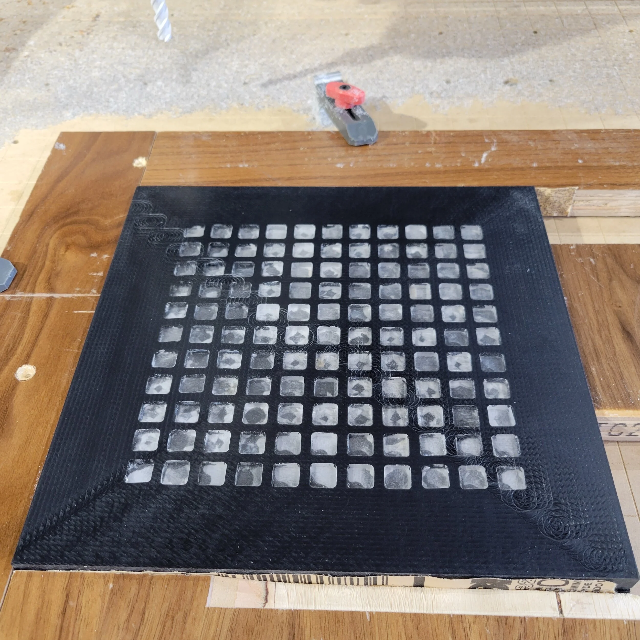
I used a 1” thick black acrylic body, with 1/4” thick clear acrylic inserts. The thick body allows the RGB panel to be nearly flush with the back so that only the electronics would protrude beyond. After inserting all the clear pieces, I surfaced it flat with the CNC and then sanded a little bit more to remove tool markings.
I then glued a walnut veneer to the front. The formaldehyde-based Ultra Cat veneer glue I usually use will not bond to plastic, so instead I used a two-part epoxy to make sure that the veneer does not move over the years. After the epoxy set, I trimmed the veneer flush and then started the engraving process for the letters.


The RGB Panel


First success with the basic clock functionality
After receiving the panel from Adafruit, I spent a few days programming on the Raspberry Pi. Using the python library Adafruit provides and adjusting a few settings to avoid screen flicker, it was just a few hours work to get the clock working. The scrolling message board took a bit longer, since I needed to figure out a way to use pre-existing bitmap fonts to render pixel-by-pixel (as the display does not have any internal intelligence).
And of course, this is where scope creep rears its head: I decided I wanted not just letters, but also to be able to display small icons or images; and to not just display in a static color, but to fully leverage the RGB capabilities to display a rainbow of colors; and to automatically have the clock dim at night, or display messages on a limited but defined schedule.
Still, compared to the 11k+ lines of code for my flight tracker, the clock is just about 1000 lines of code.
The Controls
Of course, since this clock has a whole bunch of controls to set, it needs to get its settings from somewhere! I piggybacked on the infrastructure and webserver I built for my flight tracking project to present a web interface for all the controls; the settings are initially saved on the flight tracker Raspberry Pi, and then copied over to the clock Raspberry Pi with a cronjob.


The Frame
Now I have a clock that looks great from the front, but the Raspberry Pi is just hanging out in back and not well protected or attached. I iterate on a few designs that might work, where the board is in a separate area, or perpendicular at the base for a thicker stand, and just am not that happy with the look. But then I realize the Raspberry Pi is able to just barely nestle in between some of the vertical components and connectors on the back of the RGB panel, so I can actually make a relatively sleek and slim clock.

Exploded view of internal components. Main components (from left to right) in black: clock face with engraved letters on front; white: RGB LED matrix, nestled into black; green: circuit board mount that nests the Raspberry Pi & matrix driver inside the panel; blue: spacer plastic to allow for cables and protrusion of electronics; clear: back panel with ventilation holes. Not shown are the maple and wenge wood pieces that finish the sides & lip of the frame.
First, I cut a piece of 10 mil plastic to separate the Raspberry contacts from any exposed contacts on the board, to avoid electrical shorts. The next piece is a plastic frame to attach the Raspberry to the screen itself. I fabricate a wenge border that both hides the unattractive black plastic sides of the clock, and provides a surface for EZ-Lok screw inserts for the back to screw into.
Next, the back: the Raspberry Pi protrudes out about a half inch, so with one more piece of 1/2” black acrylic (bordered with by maple), and then the final piece with ventilation holes for the back, an 1/8” brown acrylic cap.


Note that I used plastic for the internal pieces to avoid “short grain” problems that hardwood would have introduced for these narrow pieces or intricately-drilled ventilation holes.
Failures Along The Way
This might sound like a linear process from start to finish, but there were definitely a few mis-steps along the way.
When milling out the cavity in back of the face to receive the RGB panel, the stepper motors on my CNC missed a few steps and mucked it up. Fortunately, this error is completely hidden - but it was not the first time for this kind of error, so this provided the motivation to upgrade those to servo motors (stay tuned for the next post).
Similarly, when fabricating the back, when I attempted to drill for the power jack, I split the plastic. I re-cut the back, and avoided this on the second time around by using clamps to give the acrylic faces reinforcement beyond the small sliver of plastic left outside the drill bit.
And finally, when milling the outer edge of one of the acrylic pieces for the back, the double-sided tape I was using slipped; I was able to take off a little more on the sides to hide that error, filling it in with a maple border, so in fact, the recovery from this unintentional error led to an even more attractive case!
Next Version
If I were to build this again - which I definitely won’t! - these are the improvements I would make:
Translucent windows: Each clock letter is actually lit by four pixels on the RGB panel, which means that in many of the letters, you can actually see the individual LEDs since the window acrylic is transparent; instead, a milky white translucent acrylic would better blend the light from the multiple LEDs into a constant-brightness letter.
Test cut acrylic: Though I’ve done smaller projects with acrylic, this is my first project with so much acrylic (and where the acrylic fits were important). I got better at this for later cuts, but I could have benefitted from the learnings earlier: use a single-flute carbide cutter at a slower speed, and with a high air volume to keep the chips from “rewelding” to the cut plastic.
Engrave shallower letters: I cut the letters to be 1/16” deep (with a 1/32” wide end mill); while this seemed very shallow, it was still deep enough so that a wide angle view of the clock hides much of the light and thus is difficult to read.
Pour epoxy over front: I had intended to pour epoxy over the clock face, both to give it a clear glossy finish and to protect the many narrow points of the delicate veneer face. However, I had forgotten that epoxy will not bond well if a polyurethane coat is already applied, which I had done immediately after engraving to provide an initial layer of protection. Upon reviewing the epoxy directions the next day, I decided not to do a pour given the risk of destroying so much work!
Wrapping It Up

Though I haven’t done any commissions that integrate motion, sensors, electronics, or code - I can’t imagine pricing one in a way that would both reflect the time involved and be reasonable! - I’d definitely love to hear from you about collaboration opportunities on passion projects where we might have complementary skills.
And if you enjoyed this post, you may also enjoy reading about my Flight Tracker, an even more-involved project that I’ve called my pandemic child.