
In earlier posts, I shared why I upgraded (Part I) my CNC, and the sources for the main components (Part II) of it; here I’ll show all the pieces put together and share a bit more insight on the challenges in the process.
The Mundane
Bed & Lift
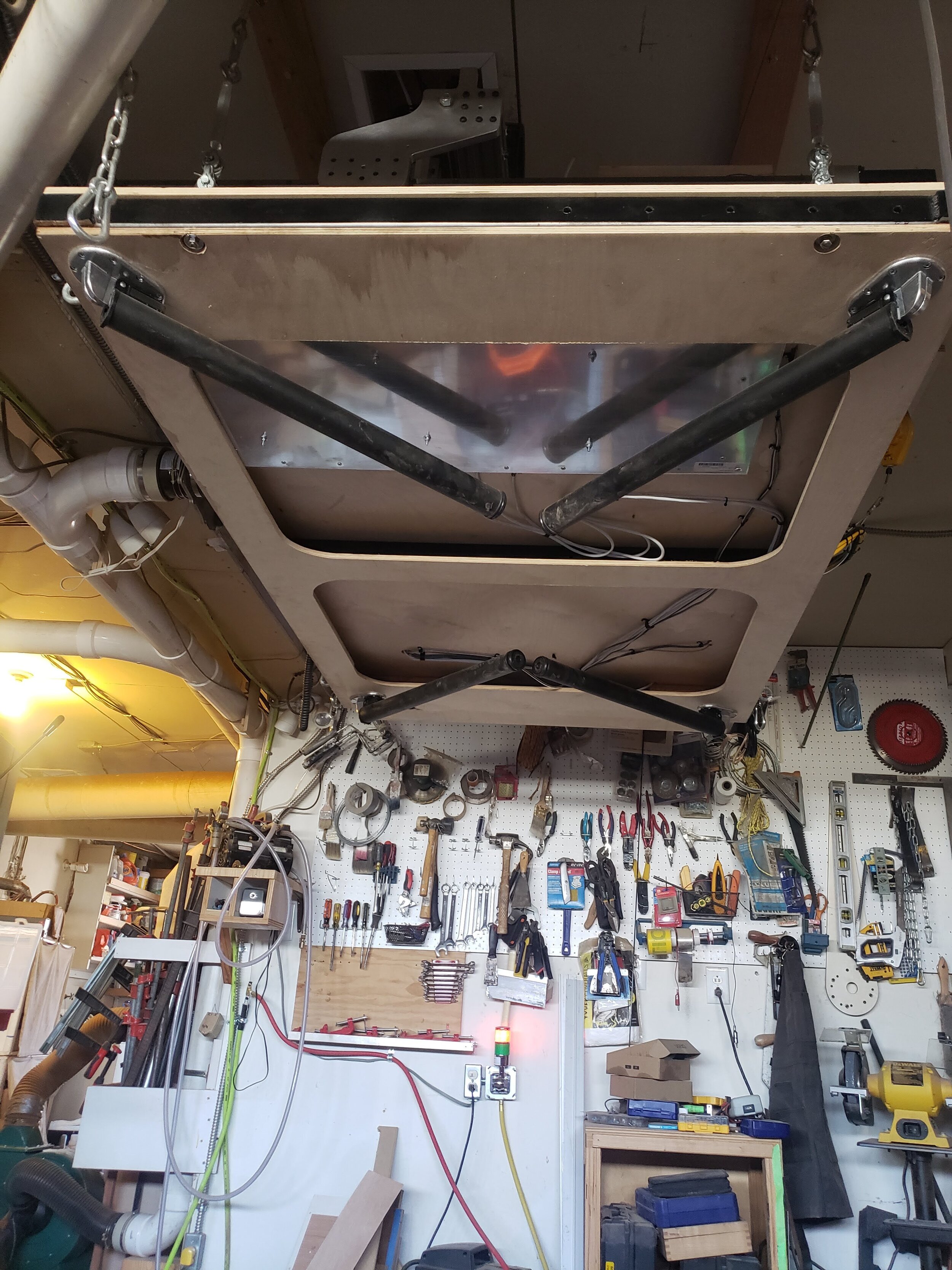
One key requirement was for my machine to be light enough to hoist overhead in my limited-space workshop. It quickly became clear that though I had weight in mind in each individual system, I was still going to blow through my 220# weight target! Though the aluminum CNC frame weighed in under 100#, the heftier spindle and stepper motors added about 30#, and the larger machine size required a larger MDF waste board as well. That’s before adding in the 4-axis & 5-axis components, wiring, etc.
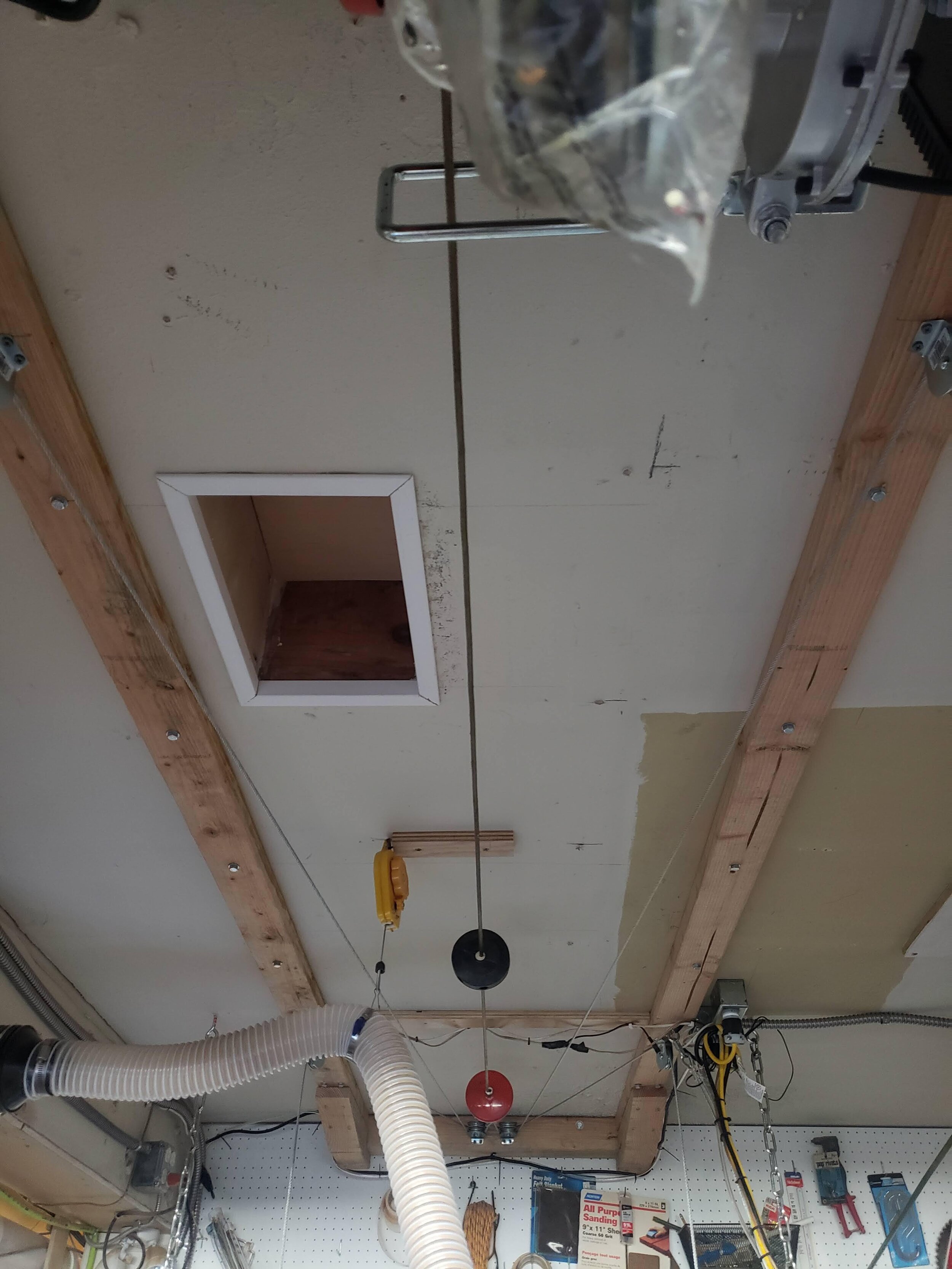
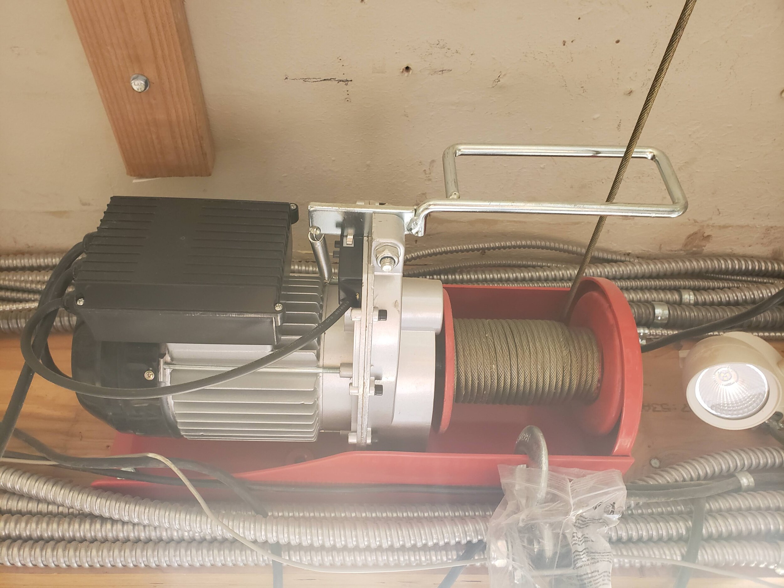
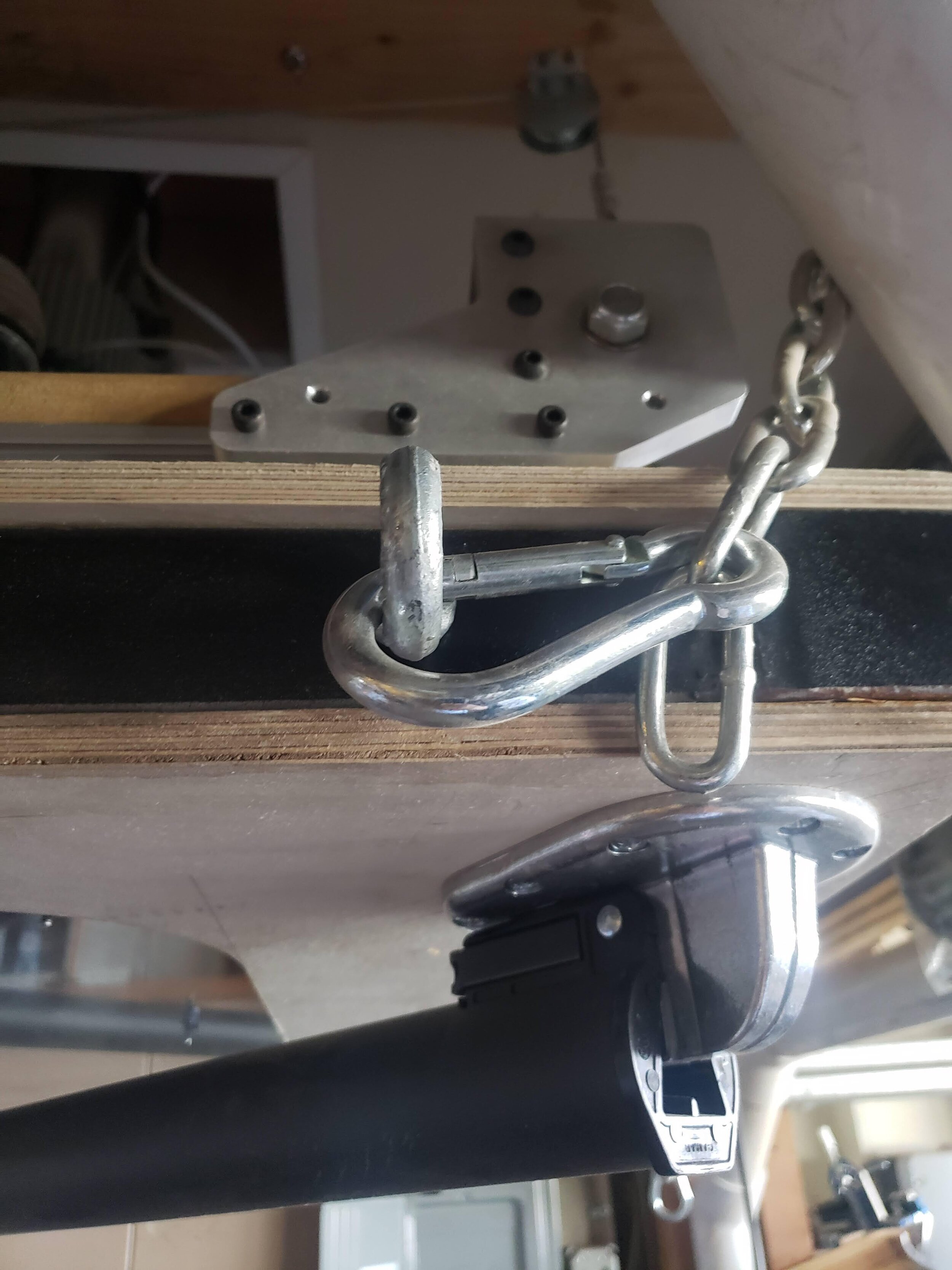
So I upgraded to a 1000# hoist, secured to the beams in the workshop, which also meant I needed to upgrade the backup earthquake protection for when the lift is in the ceiling. And to give enough headroom for the taller machine, I also cut an access hole for the z-axis protrusions above the gantry.
Frame & Controller
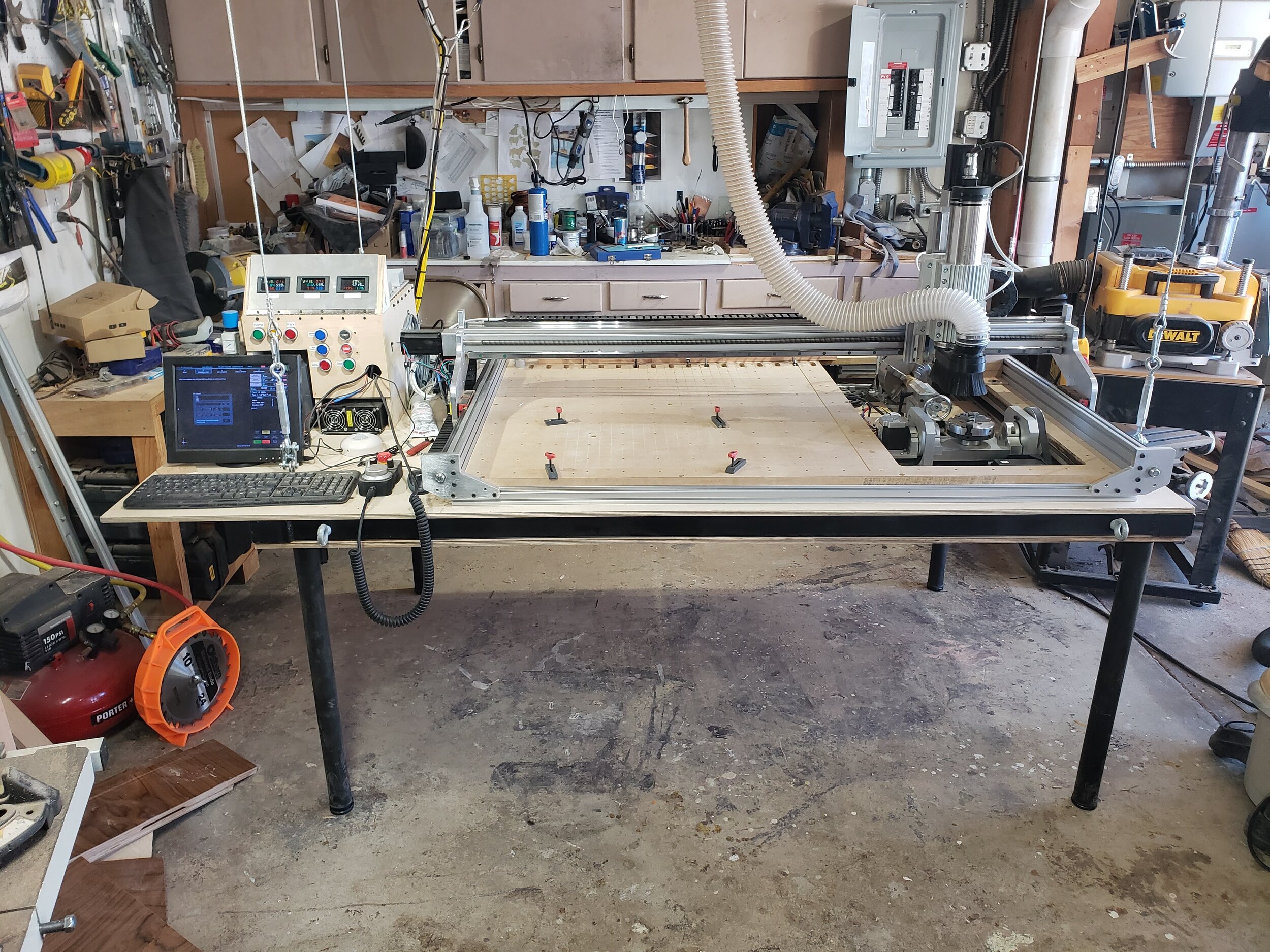
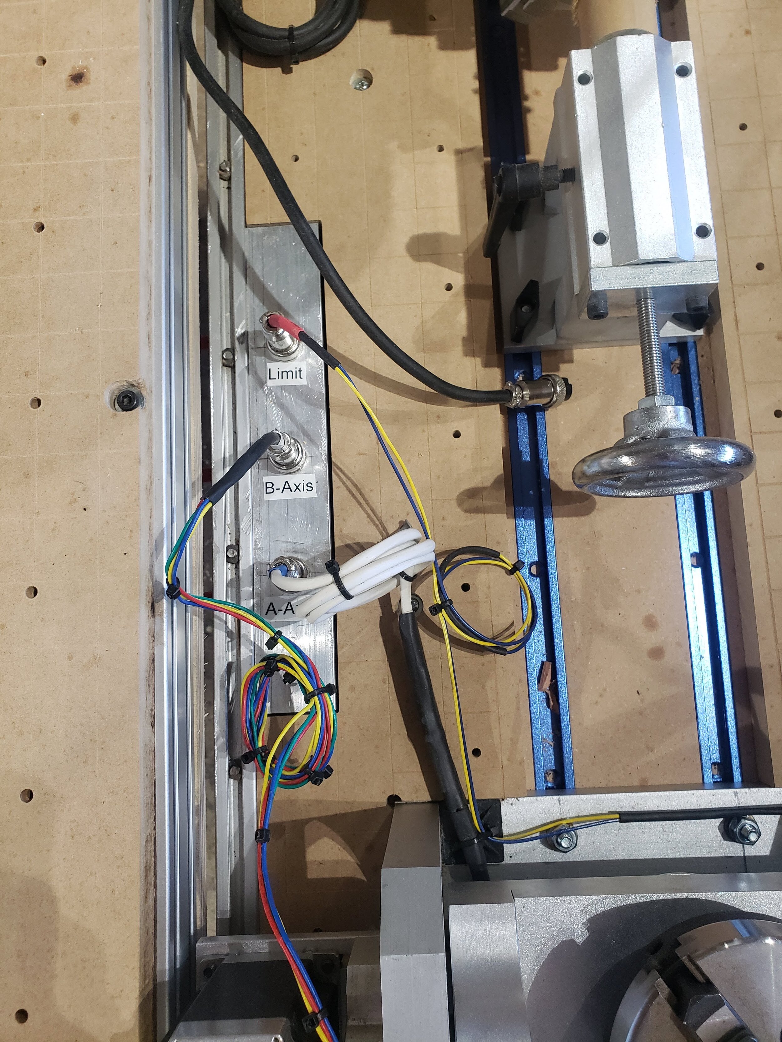
The frame - pictured in this earlier post - was relatively straightforward to assemble with the stepper motors and motor. And integrating all the sensors, limit switches, and with the highly-configurable Masso control, and setting up the stepper motor drivers, was very time-consuming and required lots of adjustments, but not particularly challenging as there were loads of Masso video tutorials.
Multi Axis Capabilities
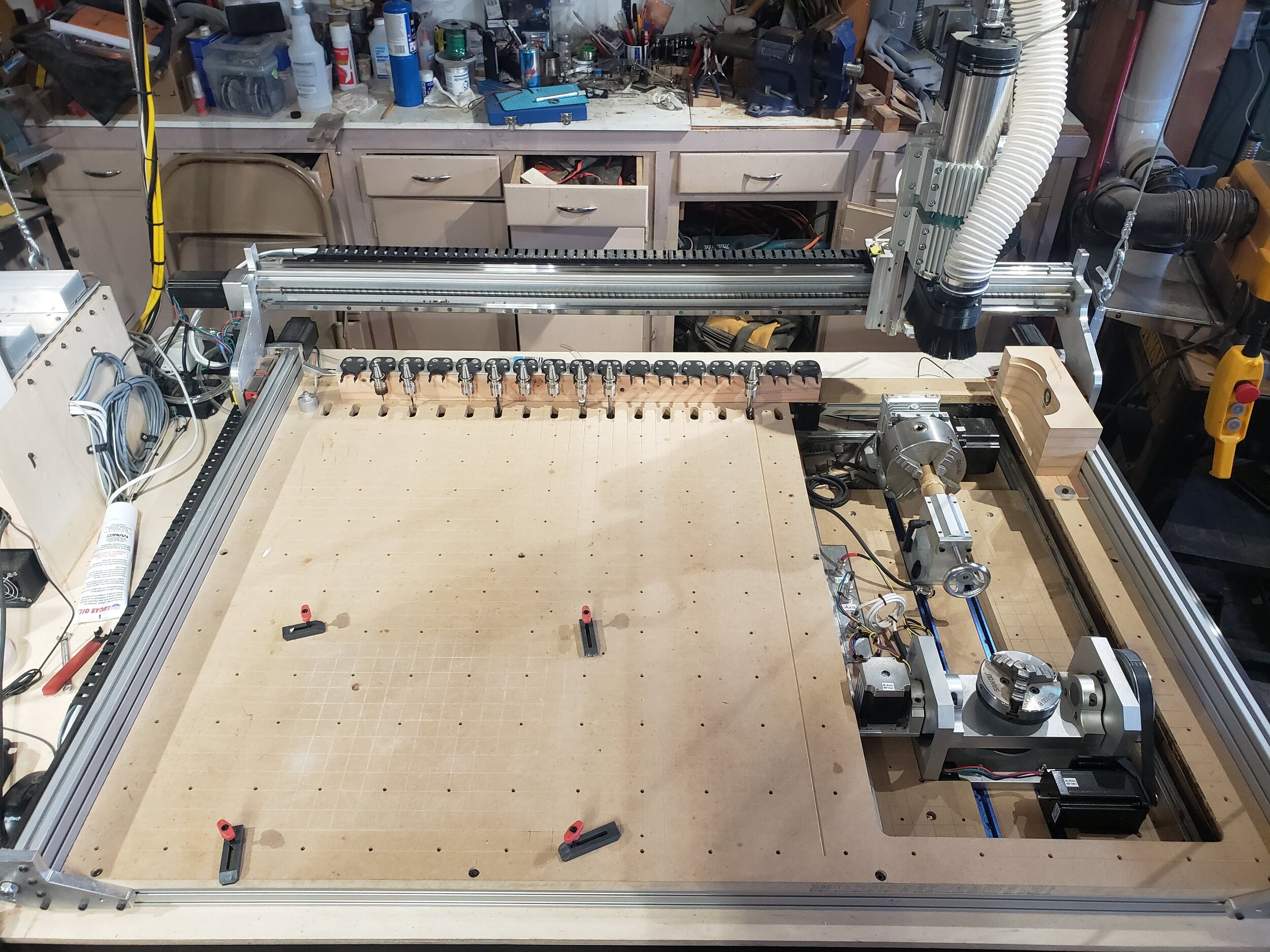
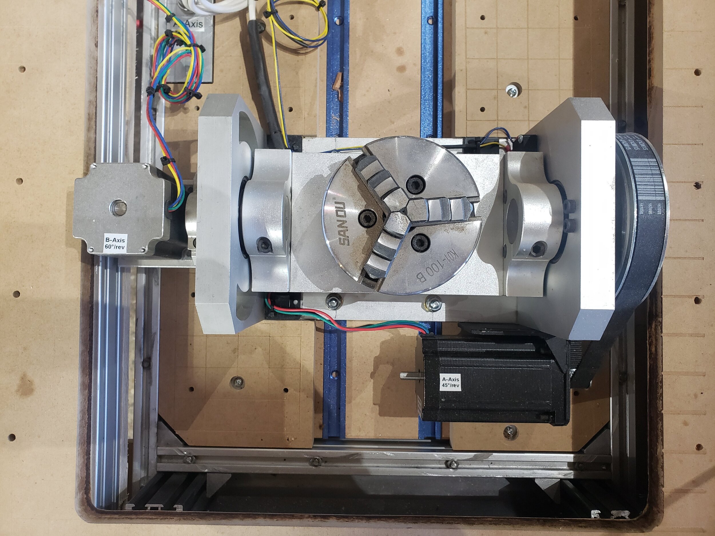
I wanted to integrate 4-axis and 5-axis capabilities into the CNC bed, and indeed, about a third of the work area is literally cut out of the MDF waste board to give more vertical clearance to these elements. But I wanted to do this in a way that provided that most flexibility for a range of jobs. I can remove the screws holding these 4-axis and 5-axis systems into the T-track so that I can use the full 48” width of the CNC to cut large profiles. Or I can use the hold-downs in this recessed area to mill much into taller items, with an 8” vertical clearance.
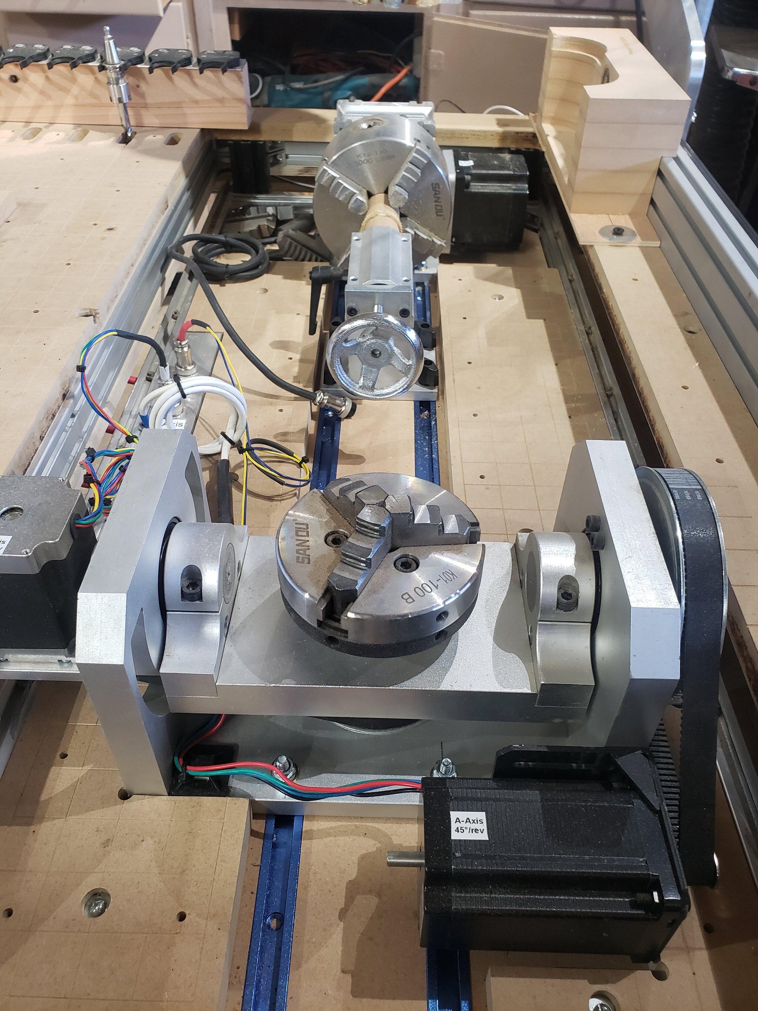
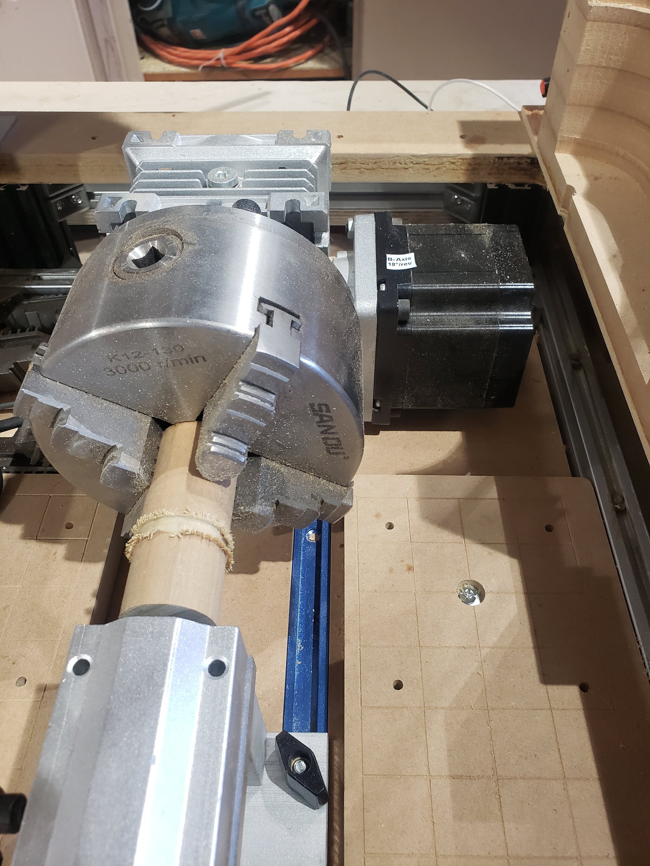
The other small customization I did in this area was to reverse the orientation of one of the motors in the 5-axis system; this allowed me to fit the assembly in the limited x-axis space of the recessed area. While I wish it was as simple as just flipping the motor around, I actually needed to customize a stepper motor mount, buy a new motor, and find a longer-but-matching-profile belt to fit into the change in position. While none of these steps was particularly difficult, it actually took a bit of sleuthing to find the right belt profile and a supplier.
Unfortunately, it seems that just as I added the capability to do rotary and 5-axis milling, Autodesk changed their pricing model from including those features in their standard paid subscription (which I have at about $300/yr) to charging an additional $1,600/yr premium! So I’ll be looking into other solutions for this - DeskProto seems like a promising CAM solution. Stay tuned for more content on this in future posts.
Tool Changer Magazine
The automatic tool changer system came with a 10-tool rack; using Mechatron’s design as a template, I built a 16-tool version to leverage more of the space available on my machine. But when I tried to actually use it, it seems I neglected to consider that differences in how deeply the collet can tighten on the tool means that some tool holders will sit higher than others. Unable to detect or handle these differences in height, the tool changer will either collide with or just completely miss some of the tools.

The black plastic on the bottom is the 10-tool holder provided by Mechatron; next up, is the 16-tool one I made with the same geometry. However, since these hold the tools by the bottom of the collet, any differences in how far the nut screws in to hold the tool in place within the tool holder means that the top of the tool holder - which needs to be perfectly aligned with the tool changer / spindle - will mean the tool changer is at the wrong height to clamp onto the tool.

This is a close-up of the ISO10 tool forks I used, which grab onto the middle of the collet, bypassing the problem that the other tool racks had.
Setting this up quickly allowed me to understand how tool changer systems can get so expensive so quickly - in addition to the tool changer itself, each tool holder position cost about $70, between the fork, collet, and tool holder. The next size up in tooling (ER20, instead of my smaller ER16) would cost upwards of $200/position. And that’s before the cost of the tool itself.
So I had to take a completely different approach to the tool magazine. I found ISO10 ER16 “tool forks” from a supplier in China; they were surprisingly expensive for their size and - perhaps because so few machines of this “small size” have tool changers - there did not seem to be any alternative suppliers or sources for them. But they indeed solved the problem.
The Challenging
Electrical Noise
Once I got all the basic motor wiring in place, it was time for a system test - but the stepper motors were making weird noises and skipping loads of steps, losing their position for even basic “out and back” moves. This one took a while to troubleshoot, and ended up being two problems.
Stepper Voltage
Though I originally was driving the stepper motors with 52V based on the equation 32 * sqrt(inductance) in this introduction, it seemed this was the culprit for the bulk of the motor jitters: lowering the voltage to 20V cut the positional error from about 10% to perhaps 1%.
After a query to ElectronicsStackExchange, I got some guidance as to why a lower voltage was necessary, but I’ll confess that my electrical engineering understanding does not extend deeply enough to fully grasp that explanation. Regardless, my updated settings (lower voltage; fewer microsteps; lower acceleration) seem to work.

These three power meters were invaluable in the initial setup and will also be helpful to identify any problems during use, or any points at which I might be overstressing the spindle or power supply.
Grounding
I was able to isolate the remaining error to the spindle controller VFD (variable frequency drive), a solid state device that converts “standard” two phase power to a three phase signal. Though I do not fully understand the solution here either, I was able to remove the noise by changing the ground wire configuration between the VFD, spindle, and aluminum frame. It seems that perhaps I had created an antenna via a ground loop that removing some of those connections solved - though that loop is probably formed with some non-obvious control wires and is dependent on the VFD being powered on.
Bonus Video
In troubleshooting these issues, I came across this excellent video where James works through some similar issues with his VFD. The two solutions that worked for him - a line noise filter and ferrules around the motor cables individually and collectively - did not solve my problems, though I imagine they may nonetheless help at the margins.
2021 Update
After all these updates, months later, I would still every once in a while get a missed step; I finally bit the bullet and upgraded to closed loop servo motors, which I document in great detail here.
Dust Collection & Tool Changer
Two key elements of my system were initially somewhat incompatible with off-the-shelf solutions: dust collection and the automatic tool changer. In short, if the tool holders are spaced tightly together, the height of the tool holder will hit any dust boot. Only if they are spaced more than 1.5x further apart would the tool holders clear the dust boot, which would mean I’d be constantly swapping tools into and out of the magazine, negating much of the value of the tool changer.
So I created a novel solution here. I used a two-piece dust boot from TiteCNC, where the top portion is attached to the spindle, and the bottom portion with the bristles is held in place via four magnets. That magnetic connection of the bottom portion, however, can be overpowered by an electromagnet grabbing onto the boot from the side. Thus, every tool change is sandwiched by first dropping off the dust boot, and afterwards, picking it back up.

The two-part dust boot is connected via a 2.5” hose to the new 4” PVC pipe runs along the ceiling.

The electromagnet - which can just barely be seen on the right embedded in the MDF - grabs onto the fender washer bolted into the removable dust shoe on the left. See it in action in the video below.

The 4” Schedule 40 PVC piping I installed throughout the workshop reduced the trip hazards in the workshop, enabled easier connection to the CNC, and led to better air flow to the tools.
For those interested in the weeds, to achieve this, I modified the Fusion360 postprocessor to inject a line that calls a subprogram before and after each tool change. That subprogram, in addition to doing the movements, also triggered the electromagnet via a relay with one of the customizable auxiliary outputs on the Masso controller.
These dust boot drop off / pick up operations were necessary for me to make sure the dust boot doesn’t collide with the tool rack of the automatic tool changer. It also allows me to park the boot (and turn off the vacuum) for certain operations where the boot would interfere or just not be that helpful.
Fully Integrated System

This MDF prototype of a 17th century hard-carved chest is only possible with the combination of my CAM upgrade to DeskProto and the speed of my new machine.
This whole process took about twice as long as I expected (and still is not complete, what with a probe to still integrate and a few other elements to fine-tune)! Partly because I was waiting for parts as I solved one problem only to find the next. And partly because I was “distracted” by other projects, both paid and personal, not focusing on this 100% of the time. But I’m excited to finally be able to say “done” - or at least, as done as any workshop upgrade ever is!
In future posts here and on Instagram, I look forward to sharing some of the creations that come from this new machine!
This deep hole in solid oak would have taken over an hour to make with my older machine due to its performance limitations.