
My compact but impossible-to-maintain electrical cabinet / control panel.
If you’ve read my earlier post about integrating the FrankenCNC, you already know there’s a lot of electrical gear that has to work in concert: stepper controllers, a tool height setter, a dust boot electromagnet, pneumatics for the tool changer—you name it.
What I didn’t emphasize back then was where all of that hardware actually lived. Every single piece was crammed into one ultra-compact control box. At first, I was proud of the puzzle-like packing job. Everything fit! But the layers of stacked components quickly turned wiring into chaos. Making or adjusting connections buried deep inside meant pushing other wires aside—risking loose connections, or worse, short circuits.
On larger CNC setups, you’ll often see a dedicated electronics cabinet to give all that hardware some breathing room. I didn’t have that luxury: my FrankenCNC hides up near the ceiling of my eight-foot-tall workshop, and space is at a premium. The cramped box made troubleshooting painful and any thought of upgrades... well, discouraging.
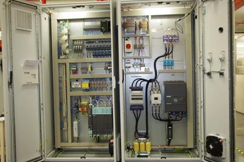
What an industrial CNC electrical cabinet might look like.
What I might aspire to for a bespoke shop-built electrical layout if space were not an issue.
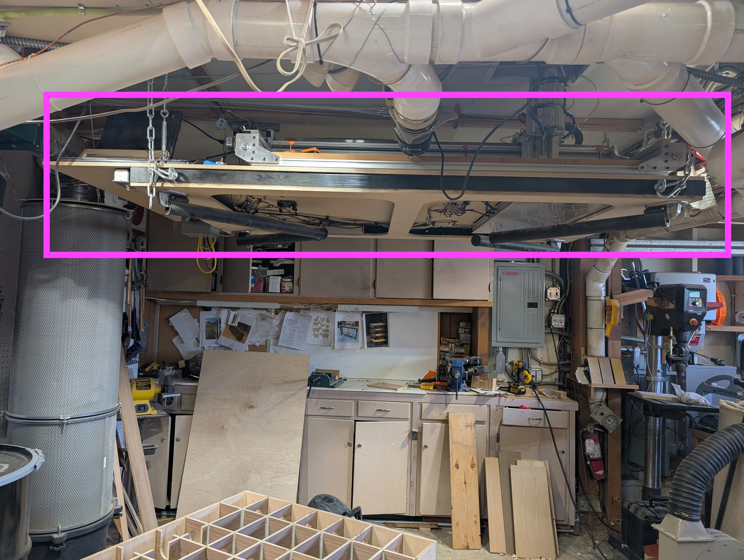
But space is an issue: the CNC nestles up against the ceiling, with a cutout in between my upstairs floor joists to fit the height of the spindle. I have only about 10” of height above the table to stay clear of the winch cables, which doesn’t give much allowance to mount components vertically or to stack in a serviceable manner.
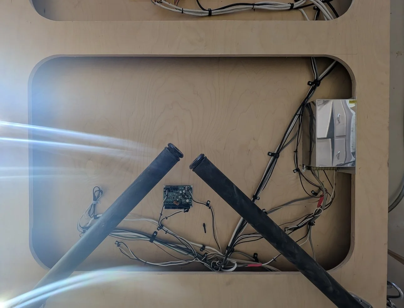
A few easier-to-service components I mounted on the underside of the table: a large regulated 24V power supply, and the Teknic servo power monitoring & distribution block.
I wish I had a photo of the tangled “rat’s nest” that lived inside that panel, but honestly, it’s probably for the best that I don’t. Some messes are better remembered than documented.
So, it was time for a fresh start—a complete rebuild of the control panel.
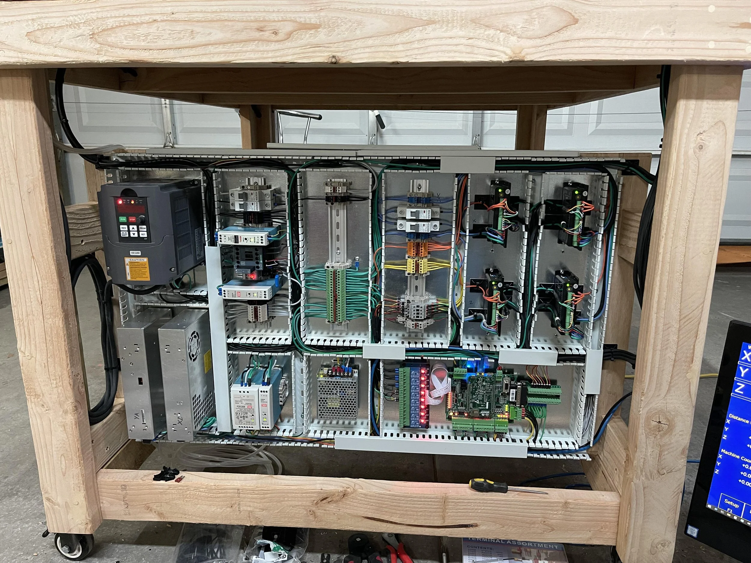
New Control Panel
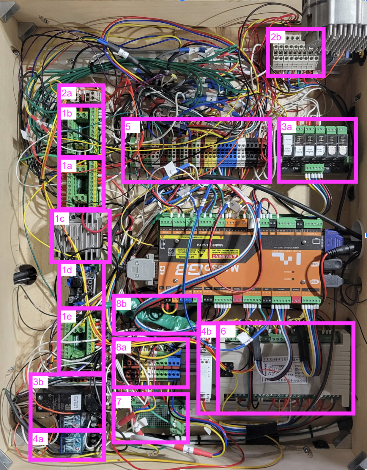
Now, it’s a labeled and structured rats nest!
If you’re interested in the nitty gritty: 1) Power distribution; 24V supply under table; 1A. 24V power distribution, not current limited (i.e.: relays, solenoids, electromagnets); 1B. 24V current-limited (fed by 1a) current-limited to reduce risk of fatal (to electronics) short circuits, for electrical control signals; 1C. 12V buck converter (for pneumatics relays & e-stop relays); 1D. 5V digital converter (for laser pointer); 1E. 12V power distribution; 2) Signal distribution block; 3A. 6-signal TTL relay for e-stop, laser, tool clamp, and dust boot; 3B. E-stop relays to sever power to spindle & servos when e-stop button pressed; 4) Pneumatics VFD-triggered relays; 4A. Mechatron tool changer positive pressure relay, on when VFD has power; 4B. Latching relay triggered by remote control to turn on / off dust-clearing air blast; 5) Signal distribution, to allow me to organize & group the long wire runs that route to the CNC from the shorter wires within the electrical panel.; 6) Remote control relay block, with an 18-button remote and 18 individual SPDT relays; 7) Touch probe wiring / in-line resistor; 8) Power monitoring; 8A. Power monitoring signal distribution; 8B. Shunt resistor for DC current monitoring
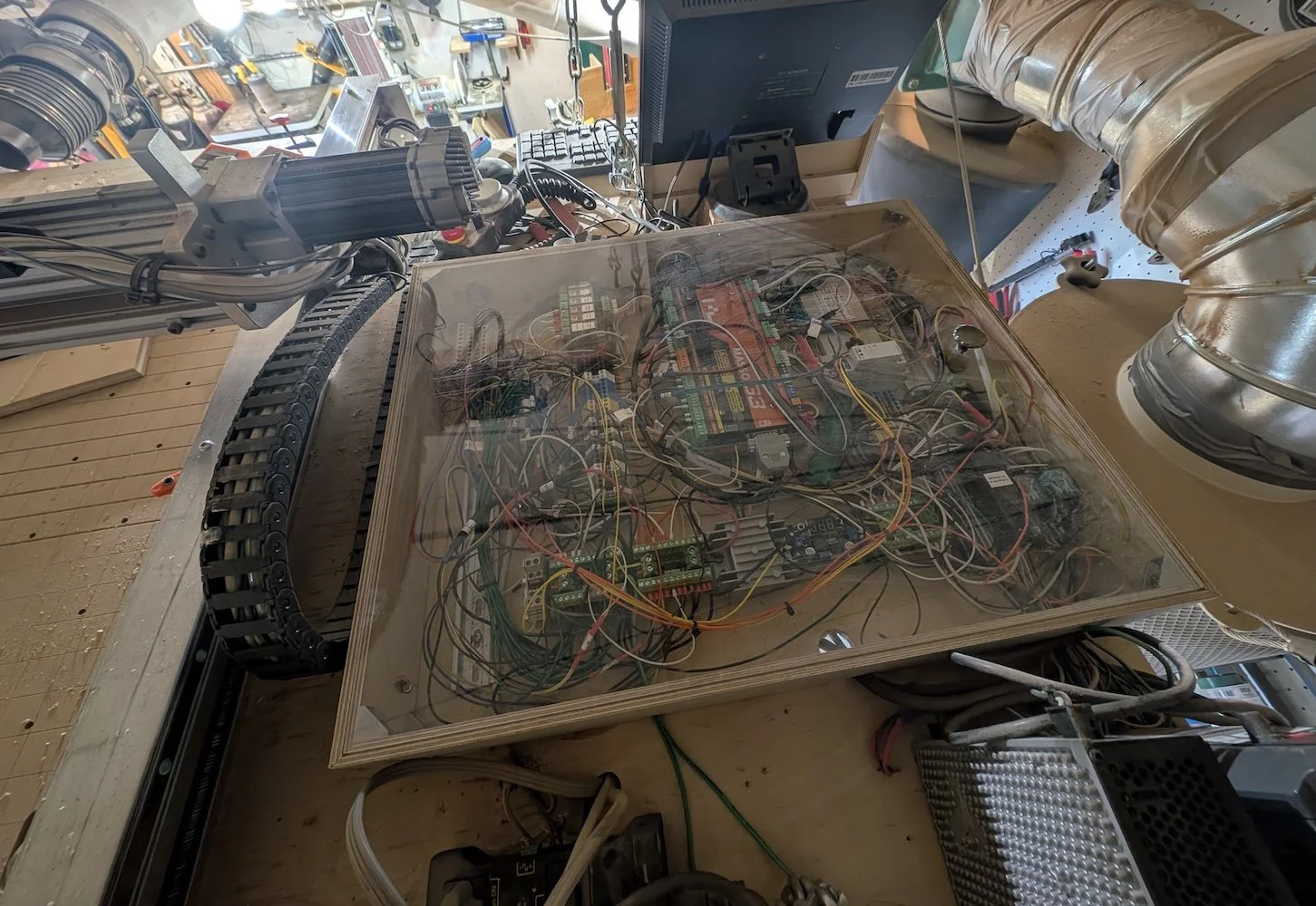
Control panel in storage, nestled between CNC drag chain and dust collector filter canister, and the ceiling.
It’s still a bit of a rat’s nest in there—but compared to the earlier control panel, the new setup has some key differences that make it far easier to live with.
What’s Changed
Single-plane layout: All components are mounted flat on one surface, not stacked in layers. No more digging through tiers of boards to reach a buried connection.
Full-panel access: The entire control area is now the access panel itself, sealed under a clear acrylic sheet instead of a small hinged door. I can see everything at a glance and remove the cover when I actually need to work inside.
Documentation and labeling: Every wire is labeled, and I’ve created a quick-reference “cheat sheet” mapping out all subsystems. Future-me will thank present-me for that.
This rebuild happened alongside the big transition from steppers to servos, but it also gave me a chance to slip in a few other upgrades:
An offset laser pointer to make origin positioning easier
Homing sensors for the 4th and 5th axes
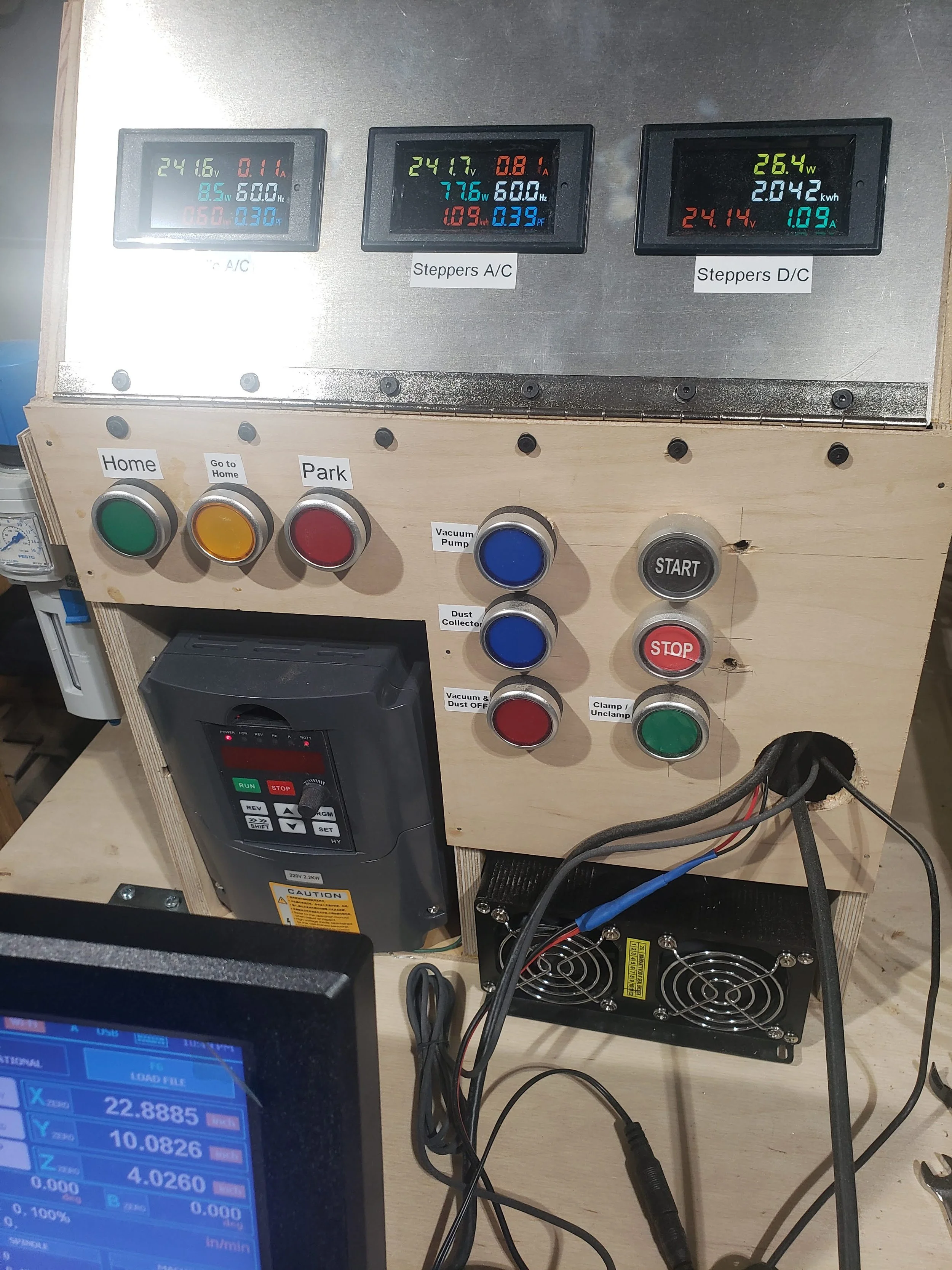
Extra manual control buttons, accessible through a wireless remoteSubsystems
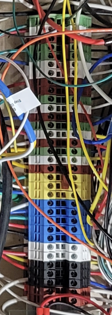
Green / White / Red (x6): are the step (green), direction (white), and error for each motion axis. The axes are, from left to right: X, Y1, Y2, Z, A, & B. The Y1 and Y2 step and direction signals are combined using a jumper, as they are slaved to each other, but that their error signals are independent. Yellow: Probe & tool setter. Blue: Homing switches; from left to right: X, Y, Z, A, & B. White: IoT relays (vacuum pump & dust collector). Black: on-gantry pneumatic solenoids. Red: +12v distribution block to relays
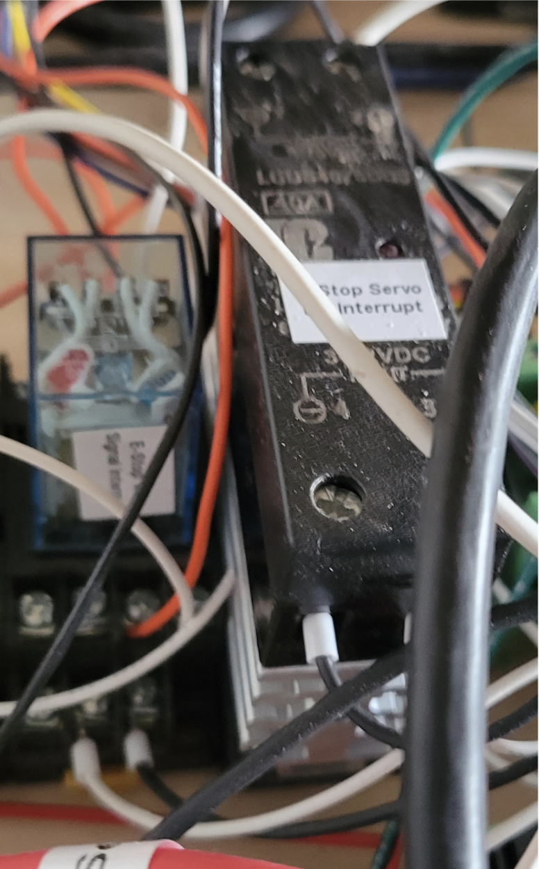
In theory, pressing the E-stop button should immediately halt servos and start spinning down VFD. But in practice (and as warned in Masso documentation), there is occasionally a delay that can cause the CNC to continue cutting, and / or only one of the two high power devices gets the signal. So we need to cut power to devices more directly using the TTL output from the controller to disconnect the spindle signal from the Masso controller (to allow a controlled spindle spin down) and Teknic DC servo bus (so all servos go into a free hold state instantly).
Cleaner Wiring
I won’t pretend it’s perfect—some cables still have minds of their own—but the difference is dramatic. Compared to the chaos of my earlier panels (and the pristine examples I’ve drooled over online), this version is functional order. Nonetheless, I found a few tools critical in stepping my work up a notch, making it easier to follow given its limitations, and less likely to cause errant shorts or have loose connections.
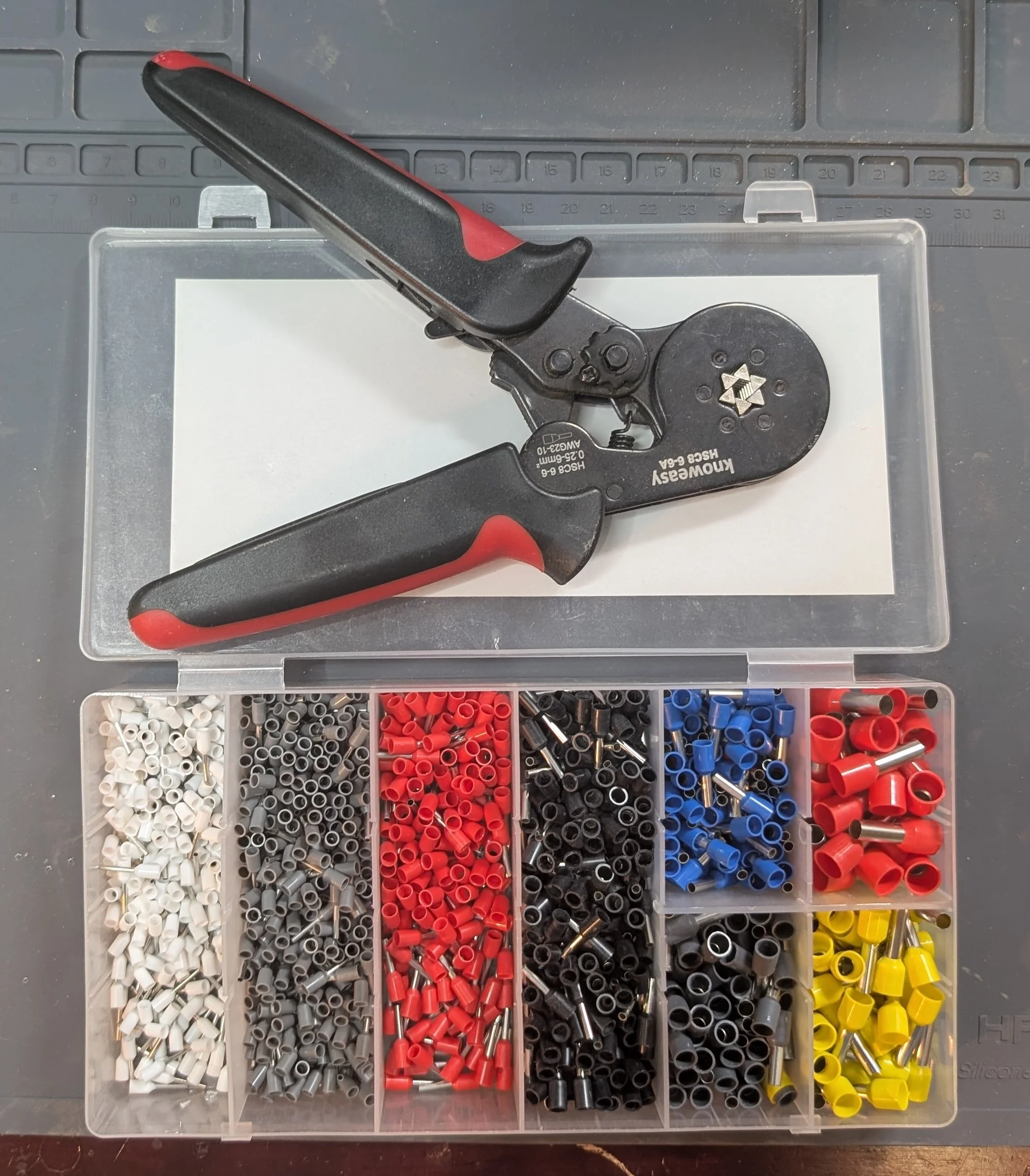
This hexagonal crimping tool and ferrule kit ensures that there are no stray wire strands that can cause short circuits - especially important for stranded wire connected to terminal blocks in close quarters.
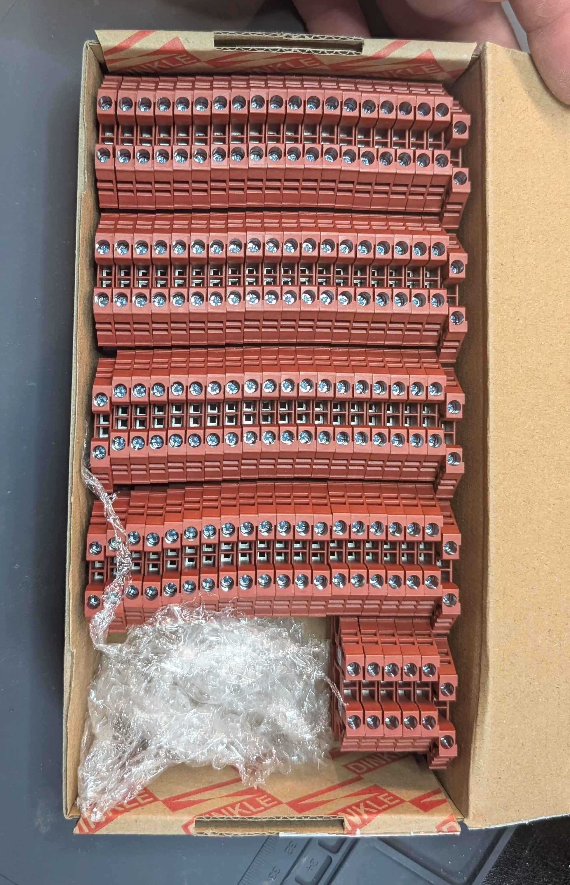
This box of red terminal blocks from Dinkle - white green, yellow, black, blue, orange, and brown - make it easier to organize connections.
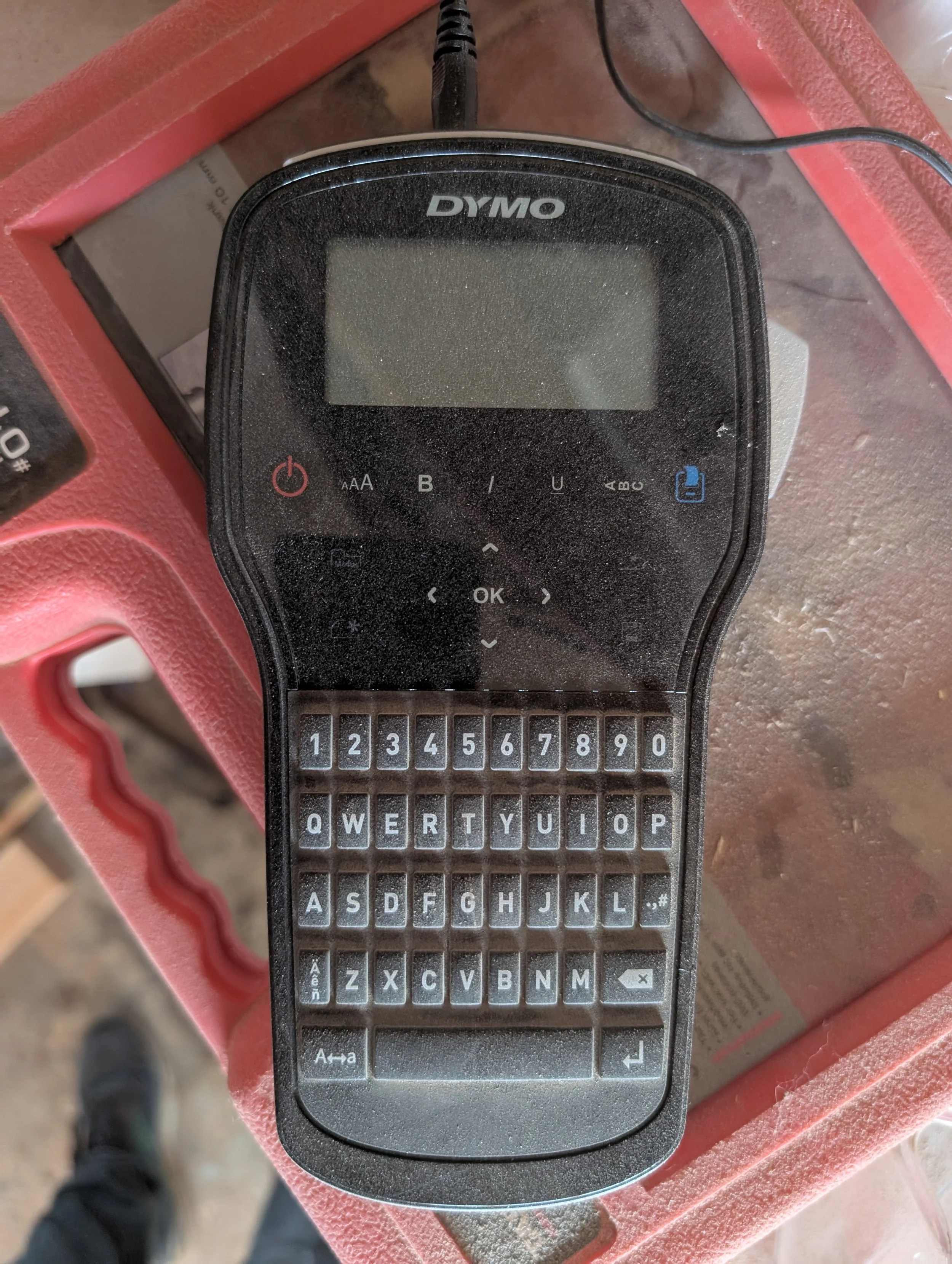
A label printer - even this inexpensive Dymo version - make labeling the connections fast and easy.
Not a “technology” per se, but I was intentional in documenting both what I did and why, and also pulling together in one place common reference sources (Teknic error codes; Masso homing switch wiring diagrams) to make it easier for my future self.
This rebuild was as much about clarity as control—both for the wiring and for me as a maker. If you’ve got a project where the “clever compact” approach has turned into a maintenance nightmare, consider giving it the space it deserves. Your future self (and your wiring) will thank you.